

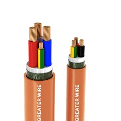
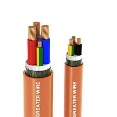

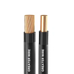


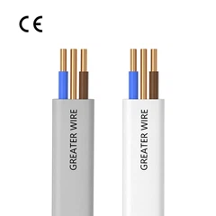
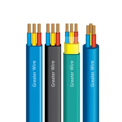
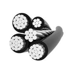


19/36kV anti-termite aluminum MV cable is mainly composed of high-purity aluminum conductors. As a conductor material, aluminum is widely used in power transmission due to its excellent conductivity and good corrosion resistance. The density of aluminum is lower than that of copper, so the weight of aluminum conductors is greatly reduced while maintaining the same conductive properties, making it easier to transport and install. In addition, the relatively low cost of aluminum helps reduce the overall project cost. High-purity aluminum has significant advantages in electrical conductivity and durability, making it suitable for medium-voltage cable systems that require long-term operation.
characteristics
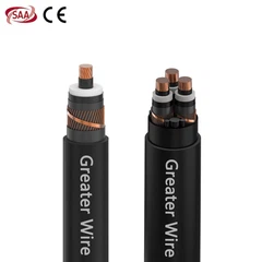
SAA single core 19/36kV anti-termite aluminum 35kV MV cable is rated at 19/36kV and safely and efficiently handles continuous medium voltage loads, ensuring stable current transmission between critical equipment. It is suitable for large-scale power supply systems, such as mining operations, oil and gas fields, port facilities, and heavy-duty industrial areas, which require long-distance, high-capacity power transmission. Compared to copper, aluminum conductors offer an economical and lightweight solution, reducing total project costs without compromising performance.

Feature

• Conductor: Stranded Compacted Circular aluminium conductor as per AS/NZS 1125
• Conductor Screen: Extruded Semi-conductive compound
• Insulation: XLPE
• Insulation Screen: Extruded strippable Semi-conductive compound
• Longitudinal Water blocking: Water blocking tape above and below copper screen (Optional)
• Metallic Insulation Screen: Copper Wire Screen + helically applied copper tape (E/F current capacity – Based on requirement)
Composite sheath
• Inner layer: Extruded Polyvinyl Chloride, Colour: Orange
• Termite Protection: Polyamide (Nylon -12)
• Outer layer: HDPE (Black)
• Min. installation temperature: 0°C
• Operating temperature: -25°C to +90°C
• Emergency operating temperature: 105°C
(max. operation of 36 hours, at 3 periods for 12 consecutive months of use)
• Max. Short Circuit Temperature: 250°C
Certification
MV cables are SAA certified, with certification numbers: SAA242046 and SAA250307 (available on the certification website). SAA certified cables are a strategic investment that ensures both immediate compliance and future resilience. Project owners can plan for long-term operations with the confidence that the cables will remain effective and reliable throughout their service life, ensuring reliable operation for decades to come..

Package


Production Line

Greater Wire Manufacturer not only provides pre-sales technical consultation but also technical support during customers' use of wires and cables. Whether installation, troubleshooting during use, or subsequent maintenance, the factory has a dedicated after-sales service team to ensure that customer problems can be solved promptly. In addition, the factory also provides regular customer return visits to understand the product's actual performance in customer projects and collect feedback for product improvements.
Case

Partner
FAQ
Q: How to determine cable faults?
1. Observe the appearance of the cable and the surrounding environment: Observe whether the cable has obvious damage, breakage, burn marks, or insulation sheath damage caused by high temperature or mechanical damage. Look for signs of water seepage, corrosion sources, or mechanical construction damage near the cable, especially underground cables are greatly affected by the external environment.
2. Insulation resistance test: Use a megohmmeter to detect the insulation resistance of the cable, usually measuring the insulation resistance of each phase of the cable to the ground at rated voltage. A lower insulation resistance value indicates that there may be an insulation fault. If the insulation resistance of a phase to the ground is too low, it means that the phase may have a ground fault.
3. Cable withstand voltage test: Apply high voltage to the cable insulation layer and keep it for a period of time to see if the cable insulation can withstand it. If the cable cannot withstand this voltage, it usually breaks down, indicating that the insulation has been damaged.
4. Fault locator measurement: Use the transmission characteristics of the signal in the cable to detect the reflected signal waveform, and determine the location and type of the fault point by the location of the abnormal waveform. The TDR method is suitable for finding open circuit, short circuit, low resistance and high resistance faults of cables. By applying high voltage pulses to the cable and measuring the time difference of the pulses reflected back at the fault point, the fault location can be calculated. It is suitable for high resistance and low resistance faults. Combining high voltage pulses and pulse currents, a short arc is formed by high voltage breakdown of the fault point, and the reflected arc signal is measured to locate the fault, which is especially suitable for high resistance faults.
5. Bridge method test: Such as Wheatstone bridge or pulse bridge, the bridge principle is used to convert the resistance imbalance of the fault point into measurement data to determine the distance of the fault point, which is suitable for finding faults such as short circuit or grounding.
6. Partial discharge detection: It is used to identify tiny discharge activities in cables. Partial discharge is an early sign of insulation degradation. By detecting the location and intensity of partial discharge, cable hazards can be identified before the fault occurs. Some high voltage cables are equipped with online monitoring systems that can monitor the partial discharge of cables in real time, helping to warn of insulation aging and fault risks in advance.
7. Infrared thermal imaging: Using an infrared thermal imager to scan the cable line, local heating points caused by poor contact or aging can be found. Particularly suitable for monitoring overheating problems of cable joints and terminals.
8. Fault type analysis
Low resistance fault: generally caused by short circuit between cable cores or core to ground.
High resistance fault: mostly caused by cable aging, insulation damage, moisture, usually accompanied by partial discharge.
Flashover fault: intermittent fault, the cable will show fault only when it is subjected to external stress or high voltage shock, common in aging cables or humid environments.
9. Verification test and confirmation
After the fault is repaired or the cable is replaced, conduct comprehensive tests (such as withstand voltage test, and insulation resistance test) to ensure that the fault has been completely eliminated and the cable system has returned to normal.
Q: What are the construction requirements for medium voltage cables?
It is necessary to confirm the laying distance and try to choose the shortest and safest laying path to avoid excessive bending or mechanical damage.
The laying path should be cleaned well, and there should be no obstacles such as stones, debris and water accumulation on the laying path that affect the laying.
The cable should be kept away from corrosive environments, heat sources, and flammable areas, and a protective tube should be installed if necessary.
Q: What is the installation temperature range for MV cables?
Hot Tags: saa single core 19/36kv anti-termite aluminum 35kv mv cable, China saa single core 19/36kv anti-termite aluminum 35kv mv cable manufacturers, suppliers, factory


|
No. of
Cores
|
Core Cross
sectional
Area
|
Nominal Diameter
|
||
|
Under
metallic
screen
|
Under
metallic
screen
|
Overall
|
||
|
No.
|
mm2
|
mm
|
mm
|
mm
|
| 1 | 50 | 27.2 | 29.1 | 36.0 |
| 1 | 70 | 28.8 | 30.7 | 37.0 |
| 1 | 95 | 30.4 | 32.3 | 39.0 |
| 1 | 120 | 32 | 33.9 | 41.0 |
| 1 | 150 | 33.3 | 35.2 | 42.0 |
| 1 | 185 | 35 | 36.9 | 44.0 |
| 1 | 240 | 37.2 | 39.2 | 46.0 |
| 1 | 300 | 39.5 | 41.4 | 49.0 |
| 1 | 400 | 42.2 | 44.1 | 52.0 |
| 1 | 500 | 45.6 | 47.5 | 55.0 |
| 1 | 630 | 48.8 | 50.7 | 59.0 |
| 1 | 800 | 52.7 | 54.6 | 63.0 |
| 1 | 1000 | 57.2 | 59.1 | 68.0 |
|
No.of Cores
|
Core Cross sectional Area
|
Max. DC Resistance at 20˚C
|
Max. AC Resistance at 90˚C
|
Approx. Capacitance
|
Approx. Inductance
|
Approx.
Reactance |
Continuous Current Rating
|
|||||
|
In ground at 20℃
|
In Duct at
20℃
|
In air at 30℃
|
||||||||||
|
Flat |
Trefoil
|
Flat
|
Trefoil
|
Flat
|
Trefoil
|
|||||||
|
No.
|
mm2
|
Ω/km
|
Ω/km
|
µF/km
|
mH/km
|
Ω/km
|
Amps
|
|||||
| 1 | 50 | 0.641 | 0.822 | 0.14 | 0.500 | 0.157 | 157 | 152 | 146 | 142 | 189 | 184 |
| 1 | 70 | 0.443 | 0.568 | 0.15 | 0.464 | 0.146 | 192 | 186 | 178 | 176 | 236 | 230 |
| 1 | 95 | 0.32 | 0.411 | 0.17 | 0.443 | 0.139 | 229 | 221 | 213 | 210 | 287 | 280 |
| 1 | 120 | 0.253 | 0.325 | 0.18 | 0.422 | 0.132 | 260 | 252 | 242 | 240 | 332 | 324 |
| 1 | 150 | 0.206 | 0.265 | 0.19 | 0.409 | 0.128 | 288 | 281 | 271 | 267 | 376 | 368 |
| 1 | 185 | 0.164 | 0.211 | 0.21 | 0.394 | 0.124 | 324 | 317 | 307 | 303 | 432 | 424 |
| 1 | 240 | 0.125 | 0.161 | 0.23 | 0.377 | 0.118 | 373 | 367 | 356 | 351 | 511 | 502 |
| 1 | 300 | 0.1 | 0.130 | 0.25 | .0.363 | 0.114 | 419 | 414 | 402 | 397 | 586 | 577 |
| 1 | 400 | 0.0778 | 0.102 | 0.27 | 0.350 | 0.110 | 466 | 470 | 457 | 451 | 676 | 673 |
| 1 | 500 | 0.0605 | 0.080 | 0.3 | 0.337 | 0.106 | 525 | 530 | 510 | 505 | 760 | 750 |
| 1 | 630 | 0.0469 | 0.064 | 0.33 | 0.326 | 0.102 | 580 | 585 | 560 | 555 | 860 | 850 |
| 1 | 800 | 0.0367 | 0.051 | 0.36 | 0.315 | 0.099 | 650 | 655 | 620 | 615 | 960 | 950 |
| 1 | 1000 | 0.0291 | 0.043 | 0.4 | 0.306 | 0.096 | 715 | 705 | 670 | 665 | 1060 | 1050 |
| 20 | 25 | 35 | 40 | 45 | 50 | 55 | 60 |
| 1.08 | 1.04 | 0.96 | 0.91 | 0.87 | 0.82 | 0.76 | 0.71 |
| 10 | 15 | 25 | 30 | 35 | 40 | 45 | 50 |
| 1.07 | 1.04 | 0.96 | 0.93 | 0.89 | 0.85 | 0.80 | 0.76 |
|
No.of Cores
|
Core Cross sectional Area
|
Max. pulling tension on conductor
|
Charging Current per phase
|
Zero sequence impedance
|
Electric Stress at Conductor Screen
|
Short circuit rating of Phase conductor
|
| No. | mm² | kN | Amps/Km | Ohms/Km | kV/mm | kA, I sec |
| 1 | 50 | 2.5 | 0.84 | 1.98 | 4.1 | 4.7 |
| 1 | 70 | 3.5 | 0.9 | 1.73 | 3.9 | 6.6 |
| 1 | 95 | 4.75 | 1.01 | 1.57 | 3.7 | 9.0 |
| 1 | 120 | 6 | 1.07 | 1.49 | 3.6 | 11.3 |
| 1 | 150 | 7.5 | 1.13 | 1.43 | 3.5 | 14.2 |
| 1 | 185 | 9.25 | 1.25 | 1.37 | 3.4 | 17.4 |
| 1 | 240 | 12 | 1.37 | 1.32 | 3.3 | 22.6 |
| 1 | 300 | 15 | 1.49 | 1.29 | 3.2 | 28.3 |
| 1 | 400 | 20 | 1.61 | 1.26 | 3.1 | 37.6 |
| 1 | 500 | 25 | 1.79 | 1.24 | 3.0 | 47.2 |
| 1 | 630 | 31.5 | 1.97 | 1.22 | 3.0 | 59.6 |
| 1 | 800 | 40 | 2.15 | 1.21 | 2.9 | 75.6 |
| 1 | 1000 | 50 | 2.39 | 1.20 | 2.8 | 94.5 |


