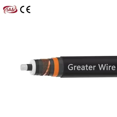
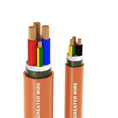
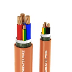

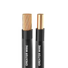
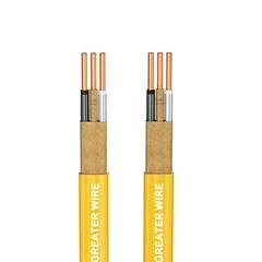
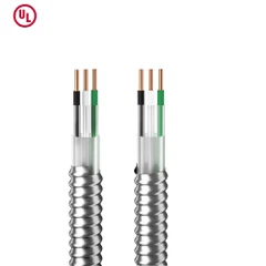
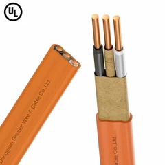
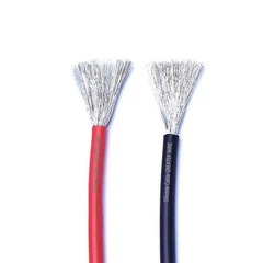
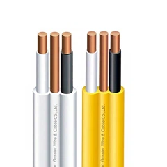
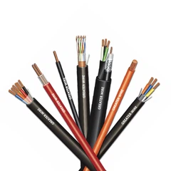
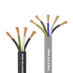
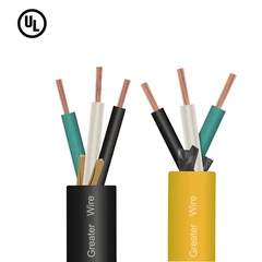
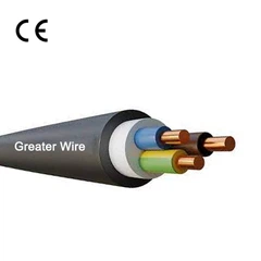
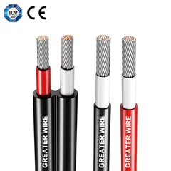

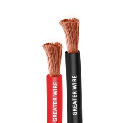
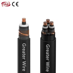
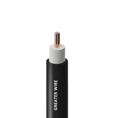
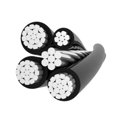
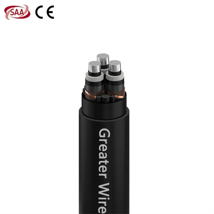
Dongguan Greater Wire & Cable Co., Ltd. is one of the leading manufacturers and suppliers of 6.35/11kv 3 core fire resistant medium voltage cable in China, also supports customized service. Please rest assured to wholesale durable 6.35/11kv 3 core fire resistant medium voltage cable made in China here from our factory. If you have any enquiry about free sample, please feel free to email us.

Fire resistant medium voltage cable takes long-term stability into consideration to ensure that it can withstand various environmental influences during use. The selection of cable materials, structural design and manufacturing process are strictly tested to ensure that the cable maintains good performance during its service life. This stability not only improves the reliability of power supply, but also reduces maintenance frequency and reduces operating costs.
Application
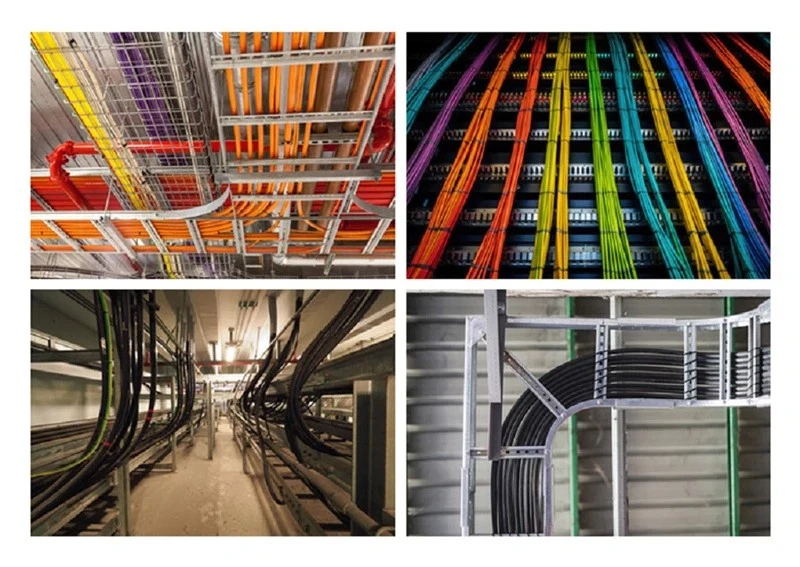
6.35/11kV aluminum 3 core fire resistant medium voltage cable is designed for critical infrastructure and public utilities where medium-voltage power distribution and fire safety are crucial. Its three core aluminum conductor design provides a balanced, compact solution for medium-voltage circuits, ensuring efficient power transmission. The fire-resistant insulation system is designed to maintain circuit integrity in the event of a fire, ensuring the operation of emergency lighting, fire pumps, alarms, and evacuation systems even in extremely high-temperature conditions.
Feature

• Conductor: Stranded Compacted Circular aluminium conductor as per AS/NZS 1125
• Conductor Screen: Extruded Semi-conductive compound
• Insulation: XLPE
• Insulation Screen: Extruded Semi-conductive compound
• Longitudinal Water blocking: Water blocking tape above and below the upper screen (Optional)
• Metallic Insulation Screen: Copper Wire Screen + helically applied copper tape
• binder tape/sheath over assembled cores
• Metallic Sheath: Lead Alloy (optional)
• Outer Sheath: Extruded Polyvinyl Chloride, Colour: Black
• Insect attack Protection: Polyamide Nylon (optional)
(Alternative Sheath: PVC + HDPE Outer Sheath or LSZH Outer sheath and parameters will change accordingly)
Certification
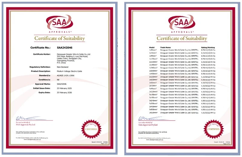
Medium voltage cable has obtained SAA certification, with certification numbers: SAA242046 and SAA250307 (available on the certification website). SAA certification systematically verifies the cable's overall quality, encompassing a comprehensive assessment of its electrical and physical properties. Certification confirms that the cable's rated voltage capability, dielectric strength, insulation resistance, flame retardancy, and corrosion resistance meet stringent specifications. Certification also demonstrates the consistent quality standards maintained by Greater Wire Manufacturer in its R&D and production.
Package

Factory

Greater Wire Manufacturer reduces production costs by optimizing production processes, improving equipment utilization, reducing energy consumption and raw material waste. At the same time, in the procurement process, the factory obtains more favorable raw material prices by establishing long-term cooperative relationships with suppliers. In addition, transportation and warehousing costs are reduced through intelligent logistics and inventory management.
Case

Partner
FAQ
Q: How flexible is the cable?
Q: What is the lightning protection performance of medium voltage cable?
Q: How to avoid short circuits in cables?
Hot Tags: 6.35/11kv 3 core fire resistant medium voltage cable, China 6.35/11kv 3 core fire resistant medium voltage cable manufacturers, suppliers, factory, 19 33Kv Aluminum Medium Voltage Three Core Cable, 3 8 7 2Kv Aluminum 3C Medium Voltage Industrial Cable, 6 35 11Kv 3 Core Copper Medium Voltage Cable, AS NZS1429 1 Single Core Aluminum 19 33kV MV Unarmored Cable, Single Core 1 9 3 3 3 6 kV Aluminum MV Cable, Three Core 12 7 24Kv Aluminum MV Cable


|
No. of
Cores
|
Core Cross
sectional
Area
|
Nominal Diameter
|
||
|
Under
metallic
screen
|
Under
metallic
screen
|
Overall
|
||
|
No.
|
mm2
|
mm
|
mm
|
mm
|
| 3 | 16 | 14.6 | 16.1 | 39.0 |
| 3 | 25 | 15.9 | 17.4 | 42.0 |
| 3 | 35 | 16.9 | 18.4 | 44.0 |
| 3 | 50 | 18 | 19.5 | 47.0 |
| 3 | 70 | 19.6 | 21.1 | 51.0 |
| 3 | 95 | 21.2 | 22.7 | 54.0 |
| 3 | 120 | 22.8 | 24.3 | 58.0 |
| 3 | 150 | 24.1 | 25.6 | 61.0 |
| 3 | 185 | 25.8 | 27.3 | 65.0 |
| 3 | 240 | 28.1 | 29.6 | 70.0 |
| 3 | 300 | 30.3 | 31.8 |
75.0 |
| 3 | 400 | 33 | 34.5 | 81.0 |
| 3 | 500 | 36.4 | 37.9 | 89.0 |
|
No.of Cores
|
Core Cross sectional Area
|
Max. DC Resistance at 20˚C
|
Max. AC Resistance at 90˚C
|
Approx. Capacitance
|
Approx. Inductance
|
Approx.
Reactance |
Continuous Current Rating
|
||
| Buried direet in ground |
In a buried duct
|
In Air
|
|||||||
|
No.
|
mm2
|
Ω/km
|
Ω/km
|
µF/km
|
mH/km
|
Ω/km
|
Amps
|
||
| 3 | 16 | 1.91 | 2.449 | 0.17 | 0.640 | 0.201 | 78 | 67 | 84 |
| 3 | 25 | 1.2 | 1.539 | 0.2 | 0.605 | 0.190 | 100 | 87 | 110 |
| 3 | 35 | 0.868 | 1.113 | 0.22 | 0.583 | 0.183 | 119 | 103 | 132 |
| 3 | 50 | 0.641 | 0.822 | 0.25 | 0.565 | 0.177 | 140 | 122 | 158 |
| 3 | 70 | 0.443 | 0.568 | 0.28 | 0.535 | 0.168 | 171 | 150 | 196 |
| 3 | 95 | 0.32 | 0.411 | 0.31 | 0.518 | 0.163 | 203 | 179 | 236 |
| 3 | 120 | 0.253 | 0.325 | 0.35 | 0.501 | 0.157 | 232 | 205 | 273 |
| 3 | 150 | 0.206 | 0.265 | 0.37 | 0.492 | 0.154 | 260 | 231 | 309 |
| 3 | 185 | 0.164 | 0.211 | 0.41 | 0.481 | 0.151 | 294 | 262 | 355 |
| 3 | 240 | 0.125 | 0.161 | 0.46 | 0.470 | 0.148 | 340 | 305 | 415 |
| 3 | 300 | 0.1 | 0.129 | 0.5 | 0.459 | 0.144 | 384 | 346 | 475 |
| 3 | 400 | 0.778 | 0.101 | 0.56 | 0.450 | 0.141 | 438 | 398 | 552 |
| 3 | 500 | 0.0605 | 0.079 | 0.63 | 0.440 | 0.138 | 505 | 460 | 646 |
| 20 | 25 | 35 | 40 | 45 | 50 | 55 | 60 |
| 1.08 | 1.04 | 0.96 | 0.91 | 0.87 | 0.82 | 0.76 | 0.71 |
| 10 | 15 | 25 | 30 | 35 | 40 | 45 | 50 |
| 1.07 | 1.04 | 0.96 | 0.93 | 0.89 | 0.85 | 0.80 | 0.76 |
|
No.of Cores
|
Core Cross sectional Area
|
Max. pulling tension on conductor
|
Charging Current per phase
|
Zero sequence impedance
|
Electric Stress at Conductor Screen
|
Short circuit rating of Phase conductor
|
| No. | mm² | kN | Amps/Km | Ohms/Km | kV/mm | kA, I sec |
| 3 | 16 | 0.8 | 0.34 | 3.61 | 2.9 | 1.4 |
| 3 | 25 | 1.25 | 0.4 | 2.70 | 2.7 | 2.3 |
| 3 | 35 | 1.75 | 0.44 | 2.27 | 2.6 | 3.1 |
| 3 | 50 | 2.5 | 0.5 | 1.98 | 2.5 | 4.5 |
| 3 | 70 | 3.5 | 0.56 | 1.73 | 2.4 | 6.2 |
| 3 | 95 | 4.75 | 0.62 | 1.57 | 2.3 | 8.5 |
| 3 | 120 | 6 | 0.7 | 1.48 | 2.3 | 10.7 |
| 3 | 150 | 7.5 | 0.74 | 1.42 | 2.3 | 13.4 |
| 3 | 185 | 9.25 | 0.82 | 1.37 | 2.2 | 16.5 |
| 3 | 240 | 12 | 0.92 | 1.32 | 2.2 | 21.4 |
| 3 | 300 | 15 | 1 | 1.29 | 2.2 | 26.8 |
| 3 | 400 | 20 | 1.12 | 1.26 | 2.1 | 35.5 |
| 3 | 500 | 25 | 1.26 | 1.24 | 2.1 | 44.7 |