


Tray cable (Type TC), is under NEC Article 336. It provides an efficient solution for installing feeders, branch circuits, and control cables, as multiple tray cable runs can be supported by a single cable tray system. This setup reduces the need for numerous conduit installations, significantly saving on both labor and material costs.
1. Tray Cable ( Type TC ) Description
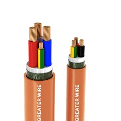
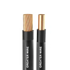
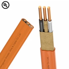
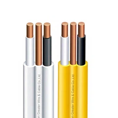
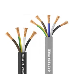
Tray Cable ( type TC ) is a factory-made and assembled cable structure that usually contains two or more insulated conductors, optionally with an associated equipment grounding conductor, and is wrapped in a non-metallic sheath. This cable is mainly used for power distribution and branch circuits and is suitable for industrial, commercial, and certain specific residential applications. The structural design of tray cable allows it to better adapt to complex wiring requirements, especially for use in cable tray systems and has obvious cost and efficiency advantages compared to traditional multi-conduit wiring methods.
Tray cable complies with Article 336 of the National Electrical Code (NEC), which allows manufacturers to choose different types of insulation materials when designing cables according to usage and needs. According to the standards listed in NEC 310.4 (A) or (B), tray cables can use different types of insulation materials, and the choice of specific types of insulation materials will directly affect the rated voltage of the cable. For example, the voltage level of tray cable can be 600 volts, 1000 volts, or 2000 volts.
In terms of cable structure design, tray cables also allow for a metal shielding layer to cover the conductor group, a metal shielding layer to be placed under the outer sheath, or even double shielding in some cases. The benefit of this design is that it can provide additional electromagnetic interference protection, allowing the cable to operate more stably in a high electromagnetic interference environment. However, according to the NEC specification, a metal sheath or armor layer is not allowed under or above the non-metallic sheath of the tray cable, which changes the cable category to a metal-clad cable (MC-type cable), which is essentially different from the structural requirements and functions of the tray cable.

2. Tray Cable Application
TC cables are used in a wide range of applications, from power, lighting control, signaling circuits to Class 1 circuits and non-limited fire alarm circuits. Due to its flexible design and excellent electrical performance, TC cables have become the first choice for many industrial and commercial locations. During installation, to ensure the long-term safe operation of the cables, they should be installed away from areas susceptible to physical damage and in many cases arranged in cable tray systems. In certain cases, cable tray systems can leave gaps (such as up to 1 foot of gap) in localized areas without the need for additional protection of the cables in these areas. This flexible design not only reduces the use of materials, but also simplifies the layout and maintenance of the cable system.
TC cables can also be installed in a variety of wiring systems, such as cable conduit systems (raceways), systems supported by steel cables or other support wires in outdoor environments, and systems connecting cable trays to power devices or other equipment. These application scenarios usually require that the cables be designed to meet the needs of specific environments, such as TC cables used outdoors should be UV-resistant, and cables used in humid or corrosive environments should be equipped with waterproof or anti-corrosion sheaths. In addition, if the TC cable is marked as suitable for direct burial, it can be directly installed under the soil or other appropriate burial materials, which is suitable for low-cost and highly concealed wiring solutions. At the same time, TC cables can also be used in explosion-proof places, but the appropriate cable type must be selected according to application requirements to ensure that the cable can withstand the dangerous factors in special places, such as high temperature, sparks or corrosive gases.
3. Types of Tray Cables
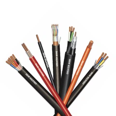
Tray Cable is divided into four different types, namely TC, TC-ER, TC-ER-HL and TC-ER-JP. These cables differ in application scenarios and physical properties, meet specific test standards and are suitable for different installation environments.
Type TC
Standard type TC cable is the most basic type of tray cable, usually used in cable tray systems, cable duct systems or outdoor installations supported by steel cables. This cable is mainly suitable for scenarios that require basic protection, requiring that the cable must always be arranged in a tray, duct or support system to ensure that it will not be damaged by external forces during operation.
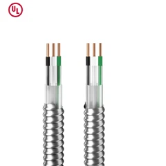
Type TC-ER
Type TC-ER cable is based on TC, with enhanced anti-extrusion and impact resistance, and meets the same pressure and impact test standards as MC cables. TC-ER cables can also maintain strong durability and stability in more demanding environments. ER stands for "Exposed Run", which means that under certain conditions, TC-ER cables can be led out of the cable tray and directly connected to power devices or other equipment terminals.
TC-ER cables are additionally tested for impact and compression resistance to ensure that they remain stable for a long time in exposed environments.
TC-ER cables for exposed operation are only installed and used in industrial locations. Such locations are usually maintained and inspected by professionals who are qualified to quickly identify and address problems in the cable system.
TC-ER cables need to be physically protected by brackets, angles, or channels to avoid physical damage caused by external impact, pulling, etc., to ensure that the cables can remain stable during operation and reduce the need for maintenance in harsh environments.
TC-ER cables must be fixed every six feet (about 1.8 meters) when they are routed.
In exposed operating conditions, the cable assembly must include an equipment grounding conductor. For conductors of 6 AWG and below, insulated conductors can be used as equipment grounding wires during installation. According to the requirements of NEC 250.119(B), these conductors need to be re-marked when they are routed.
Exception for Exposed Run
When TC-ER cable is routed between cable trays or between cable trays and electrical equipment and is not subject to physical damage, the cable support and protection requirements may be relaxed to allow the cable to be routed without continuous support or protection for a maximum of six feet and without being secured during this distance. However, the cable must be secured at the point where it leaves the cable tray to ensure stability and security during the unsupported run. This six-foot relaxation applies only when the cable is not subject to physical damage, as provided in the exception to NEC 336.10, clause (7). This arrangement allows the TC-ER cable to be routed without mechanical support or protection for a short distance of exposed sections.
Type TC and TC-ER cables are approved for use in hazardous locations under certain conditions. The installation of these cables must meet specific requirements to ensure safe operation in high-risk environments.
According to the relevant provisions of the NEC code (501.10 (A), 502.10 (B), and 503.10 (A)), TC and TC-ER cables can be used in the following hazardous zones: Class I, Division 2 (areas where flammable gases or vapors are present), Class II, Division 2 (areas where flammable dusts are present), and Class III, Division 1 and Division 2 (areas where ignitable fibers and flyings are present). These zones represent different levels of hazardous environments and require cables to meet higher safety standards in design and installation to prevent the risk of explosion or fire caused by sparks or high temperatures.
Type TC-ER-HL
Type TC-ER-HL cable is a high-performance tray cable that has undergone a number of rigorous tests, including impact test at low temperature, mechanical damage impact test, extrusion test, and flame retardant test. Through these tests, TC-ER-HL cable has excellent physical strength and fire resistance, ensuring its safety and stability when used in high-risk locations.
In terms of application scenarios, TC-ER-HL cable can be installed in Class I, Division 1 and Class II, Division 1 areas. These areas usually have explosive gases, vapors or dusts, requiring the cable to have an extremely high level of protection. In addition, when flexible connections are required, TC-ER-HL cables can also be flexibly applied under specific conditions.
TC-ER-HL cable construction and installation requirements in hazardous locations
• The outer sheath material of a TC-ER-HL cable must be suitable for the environment in which it is installed and be able to maintain integrity and durability under specified conditions of temperature, humidity, chemicals or mechanical shock.
• The cross-section of TC-ER-HL cables must be circular to be compatible with cable connectors with higher sealing properties, which can more effectively prevent harmful substances from penetrating into the connection and ensure the sealing performance of the overall system.
• The outer sheath of TC-ER-HL cables must be a continuous non-metallic material with good air tightness and vapor tightness. The outer sheath shall not have cracks, gaps or other defects that may allow gas and vapor to enter the cable.
• When the diameter of TC-ER-HL cables exceeds one inch, their equipment grounding conductors must be exposed to provide a reliable grounding path, and a metal shielding layer must be added between the conductor and the outer sheath.
See NEC 336.130
In addition to meeting the above structural requirements, the installation of TC-ER-HL cables must also meet the requirements that they are only applicable to restricted industrial areas where public access is strictly controlled and only qualified professionals are allowed to perform installation, maintenance and repair. This restriction not only reduces safety hazards caused by improper operation, but also ensures that the cables are professionally supervised and maintained during operation. The circuit voltage must not exceed 600 volts to reduce the risk of arcs or sparks that may be caused by high voltage. When installing TC-ER-HL cables, they must be protected from contact with objects that may cause abrasion, extrusion or impact. When installed in support devices such as trays and guides, it must be ensured that these support systems fully protect the cables. The terminal connections of TC-ER-HL cables in hazardous locations must use connectors suitable for the area to ensure the sealing and mechanical strength of the connections and prevent gas or vapor from penetrating into the cable system. When TC-ER-HL cables are installed in ventilated trays or guides, special attention must be paid to the arrangement and spacing of the cables to prevent the risk of fire caused by dust accumulation. This arrangement ensures adequate air circulation and reduces potential hazards caused by dust accumulation.
See NEC 501.10(A)(1)(6) and NEC 502.10(A)(1)(6)
Type TC-ER-JP
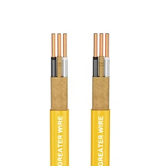
Type TC-ER-JP cables are tray cables whose "JP" designation means that the cables have additional "joist pull" capabilities. In residential buildings, TC-ER-JP cables can pass through holes in wood structures without damaging the outer sheath due to friction. When installed in wood structures, TC-ER-JP cables have higher wear resistance, reducing the risk of outer sheath damage due to friction during installation.
This cable is mainly used for generator power supply and control circuits in residential applications, providing homes with more flexible and safe power wiring options.
See NEC 336.10(9)