



When selecting cable for an industrial motor installation, electrical contractors and purchasing teams often ask whether Type TC-ER cable can be used for motor branch circuits. The short answer is yes, in certain applications, provided the cable is properly listed, rated, sized, protected, and installed in accordance with the applicable electrical code.
However, the TC-ER marking alone does not guarantee suitability for every motor circuit or installation method. Engineers must consider the motor's electrical requirements, conductor ampacity, overcurrent protection, grounding, cable routing, and environmental conditions.
This guide explains What is TC-ER Cable, how it relates to motor branch circuits, what the NEC requires, and how to distinguish TC-ER from ITC cable when specifying industrial wiring.
1. What Is TC-ER Cable?
TC-ER stands for Tray Cable–Exposed Run. It is a designation for a type of electrical power and control tray cable that is identified for certain exposed-run installations outside a cable tray.
In North America, Type TC cables are generally covered by UL 1277, Electrical Power and Control Tray Cables with Optional Optical-Fiber Members. Their installation is primarily addressed by NEC Article 336, together with other applicable NEC requirements.
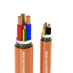
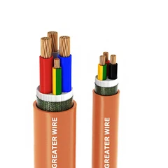
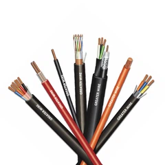
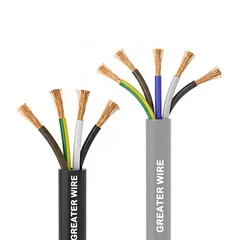
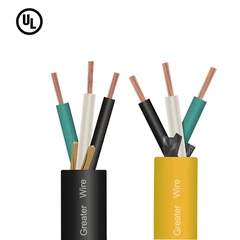
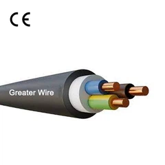
A typical Type TC cable consists of:
Two or more insulated electrical conductors.
An overall nonmetallic jacket.
An optional equipment grounding conductor.
Optional additional construction features, depending on the product design.
TC-ER products are designed to meet additional mechanical requirements for permitted exposed-run applications. This does not mean that every TC-ER cable can be installed without mechanical protection in every environment.
Common TC-ER cable characteristics
| Feature | Typical description | What buyers should verify |
|---|---|---|
| Cable type | Type TC-ER | Confirm the actual jacket marking and listing |
| Product standard | UL 1277 for applicable North American products | Check the product certification |
| Voltage rating | Many products are rated 600 V | Verify the specific cable marking |
| Conductors | Copper or aluminum, depending on product | Confirm conductor material and size |
| Insulation | Varies by cable construction | Check the insulation designation and temperature rating |
| Grounding conductor | May be included or omitted | Confirm the required grounding arrangement |
| Outer jacket | PVC, CPE, or another specified material | Check environmental and mechanical ratings |
Not every TC-ER cable has the same construction. For example, a cable may have an overall jacket but no overall shield, while another may include shielding or one or more grounding conductors.
The complete product marking and datasheet-not just the words TC-ER-should determine whether a particular cable is suitable for a motor installation.
2. Can TC-ER Cable Be Used for Motor Branch Circuits?
Yes. Type TC cable is permitted for power circuits under NEC Article 336, and motor branch-circuit applications may fall within that permitted use when all applicable requirements are satisfied.
However, three separate questions must be answered:
Is the cable product listed and rated for the intended circuit?
Does the proposed wiring method comply with NEC Article 336 and other applicable installation rules?
Does the complete motor circuit comply with the motor-specific requirements of NEC Article 430?
A cable's permission for use in a tray does not automatically establish permission for every exposed wiring route, equipment connection, or motor installation.
Cable tray installation
Type TC cable is commonly used in industrial cable tray systems for power and control wiring. When the cable is installed in a tray, the installation must comply with the applicable requirements of NEC Article 336 and Article 392.
The selected cable must also be suitable for the actual tray environment. Relevant considerations include:
Cable support and securing.
Tray fill and cable arrangement.
Ambient temperature.
Number of current-carrying conductors.
Cable temperature and voltage ratings.
Environmental exposure and mechanical protection.
Exposed-run installation
The ER designation is especially relevant when a cable needs to leave a tray and connect to a motor, junction box, or other utilization equipment.
Under NEC 336.10, Type TC-ER cable can be used for specified connections between a cable tray and utilization equipment when the applicable conditions are met. These conditions include requirements relating to the industrial establishment, qualified personnel, continuous support, and protection against physical damage.
The applicable edition of the NEC also contains specific provisions for certain short transitions without continuous support. These provisions should not be interpreted as unrestricted permission for exposed wiring.
Before using TC-ER outside a tray, verify:
The cable is actually marked TC-ER.
The installation meets the conditions of the adopted NEC edition.
The cable is protected against physical damage where required.
Mechanical support and bending-radius requirements are satisfied.
The cable is suitable for the environmental conditions.
For this reason, a properly specified NEC TC-ER Cable installation involves both product verification and installation-code compliance.
3. How Does NEC Article 430 Affect TC-ER Motor Circuits?
NEC Article 336 addresses Type TC cable applications, while NEC Article 430 addresses motors, motor circuits, and controllers.
These articles work together. Article 336 determines where and how the cable type may be used; Article 430 establishes motor-specific electrical requirements.
Motor branch-circuit conductor sizing
For a single motor operating under continuous-duty conditions, NEC 430.22 generally requires branch-circuit conductors to have an ampacity of at least 125% of the motor full-load current determined in accordance with NEC 430.6.
The calculation is not simply based on the motor's horsepower or the current printed on its nameplate. The applicable motor full-load current tables and specific code provisions must be considered.
A simplified illustration:
| Item | Example value |
|---|---|
| Motor full-load current from the applicable NEC table | 40 A |
| General continuous-duty conductor-sizing factor | 125% |
| Minimum calculated conductor ampacity | 50 A |
This is an illustrative calculation, not a final conductor selection. The actual conductor size must also account for the applicable ampacity table, terminal temperature limitations, ambient-temperature correction, conductor adjustment factors, and installation conditions.
Special motor duty classifications and other circuit arrangements may require different calculations.
Overcurrent protection is a separate requirement
Motor branch-circuit conductors, overload protection, and branch-circuit short-circuit and ground-fault protection do not all use the same sizing calculation.
For example:
Conductor ampacity is determined under the applicable motor conductor rules.
Motor overload protection is selected according to the motor and overload requirements.
Branch-circuit short-circuit and ground-fault protection is selected under the applicable provisions of NEC Article 430.
Do not assume that a circuit breaker or fuse rating can be used directly as the required conductor ampacity.
The cable must be suitable for the complete protection and operating arrangement.
What about VFD motor circuits?
When a variable frequency drive is installed between the supply and the motor, the circuit must be evaluated as an adjustable-speed drive system.
The conductors supplying the drive and the conductors between the drive and motor serve different functions. Applicable provisions of NEC Article 430, including the adjustable-speed drive requirements in Section 430.122, must be reviewed for the adopted code edition.
The drive manufacturer's instructions also matter. Output conductor sizing, cable length, insulation suitability, grounding, and any required output filtering should be checked against the specific drive and motor documentation.
A standard TC-ER cable should not automatically be assumed to be a VFD-rated motor cable.


4. What Should You Check Before Selecting TC-ER Cable for a Motor?
Even when a cable type is permitted, the specific product must meet the electrical and environmental requirements of the installation.
The following factors are particularly important.
4.1 Conductor size and ampacity
Select the conductor size according to the applicable motor-circuit calculation, not simply by matching the motor's nameplate current to a cable ampacity table.
Check:
Motor full-load current and duty classification.
Applicable NEC conductor-sizing provisions.
Copper or aluminum conductor material.
Ambient temperature.
Number of current-carrying conductors.
Cable tray installation conditions.
Terminal temperature ratings and lug compatibility.
A conductor insulation temperature rating of 90°C does not automatically permit the use of the 90°C ampacity at equipment terminals. Terminal ratings and NEC 110.14(C) must also be considered.
4.2 Voltage and insulation rating
Many TC-ER cables are rated 600 V, but the rating must be confirmed from the actual product marking.
The insulation system must also be suitable for the operating temperature, moisture exposure, and electrical conditions.
For installations involving VFDs, consider the drive output waveform, switching characteristics, motor cable length, and potential reflected-wave effects. The drive and motor manufacturers may specify particular cable constructions or additional output protection.
4.3 Equipment grounding conductor
A motor installation requires an appropriate equipment grounding path.
Some TC-ER cables include a bare or insulated equipment grounding conductor, while others may not. The grounding arrangement must comply with NEC Article 250 and the applicable motor installation requirements.
Do not assume that the cable's metallic tray, overall shield, or drain wire automatically replaces the required equipment grounding conductor.
Where the cable does not contain the required grounding conductor, the engineer or installer must determine an acceptable grounding method under the applicable code.
4.4 Environmental ratings
Industrial motor installations may expose cables to moisture, oil, sunlight, chemicals, vibration, and mechanical damage.
A TC-ER marking alone does not establish every environmental rating.
Check the product documentation for the markings and test evidence required by the project, such as:
Sunlight resistance.
Wet-location suitability.
Oil resistance.
Chemical resistance.
Temperature range.
Flame-performance requirements.
Direct-burial suitability, if required.
A cable should not be selected for an outdoor or industrial environment merely because its product description includes the words tray cable.

5. TC-ER vs ITC Cable: Which Is Suitable for Motor Circuits?
When comparing industrial cables, buyers may encounter both TC-ER and ITC products. Although both are associated with cable tray installations, their intended circuit applications are different.
Understanding TC-ER vs ITC Cable is important because a cable that is suitable for instrumentation wiring is not automatically suitable for a motor power circuit.
| Comparison factor | TC-ER Cable | ITC Cable |
|---|---|---|
| Full name | Tray Cable–Exposed Run | Instrumentation Tray Cable |
| Main application | Power and control circuits within its ratings and permitted uses | Instrumentation and related control circuits |
| Main UL standard | UL 1277 | UL 2250 |
| NEC reference | Article 336 | Article 727 |
| Typical voltage context | Many products are rated 600 V | UL 2250 cables are rated 300 V but are intended for circuits rated 150 V or less and 5 A or less under the standard's stated scope |
| Motor power circuit | May be suitable when correctly specified and installed | Generally not intended for motor power circuits |
| Exposed-run designation | TC-ER | ITC-ER when specifically marked and listed |
| Typical applications | Industrial power distribution, motor wiring, and control circuits | Process instrumentation, measurement, and control wiring |
The distinction is not simply that TC-ER has a higher voltage rating. The product standards define different cable types and intended applications.
UL 2250 covers instrumentation tray cables for specific low-voltage, low-current instrumentation circuits. A standard ITC cable should therefore not be substituted for a motor branch-circuit cable simply because it can be installed in a tray.
Likewise, a TC-ER cable should not automatically replace ITC where an instrumentation system specification or applicable code requires a particular cable type.
Practical selection rule: For a motor power circuit, evaluate a properly rated Type TC or TC-ER product where permitted. For instrumentation signals, evaluate the appropriate ITC product and its circuit limitations.
6. Is TC-ER Cable Suitable for Oil and Gas Facilities?
TC-ER cable may be considered for certain power and control applications in oil and gas facilities, but the facility's operating environment and hazardous-area classification must be evaluated carefully.
The phrase Oil and Gas Cable describes a broad market category rather than one universal cable type or certification.
An oil and gas project may include:
Motor branch circuits.
Pump and compressor power connections.
Instrumentation and control wiring.
Outdoor cable tray installations.
Process-area equipment connections.
Hazardous (classified) locations.
Each application can have different cable requirements.
Hazardous-location considerations
A TC-ER marking does not automatically authorize installation in every hazardous location.
Where a motor circuit is installed in a classified area, the applicable NEC hazardous-location provisions must be reviewed. These may include Article 500 and the relevant requirements for the specific Class, Division, or Zone.
The cable must be specifically suitable for the location and wiring method. Equipment enclosures, fittings, sealing requirements, cable entries, and other installation details may also affect compliance.
For example, a cable that is suitable for a general industrial tray installation may not be acceptable for a particular classified-area connection.
Oil resistance is not automatic
Oil and gas facilities may expose cables to lubricants, hydraulic fluids, fuels, and process chemicals.
However, not every TC-ER cable is oil-resistant. Buyers should check whether the product carries the required oil-resistance marking and whether the test method or rating matches the project specification.
For international projects, confirm the applicable certification and installation requirements in the target market. UL listing does not automatically establish compliance with CSA, IEC, or AS/NZS requirements.

7. How to Evaluate a TC-ER Cable Factory
For distributors, electrical contractors, and OEM purchasing teams, selecting a cable supplier is also part of the technical evaluation.
When contacting a TC-ER Cable Factory, buyers should request more than a price quotation. The supplier should be able to identify the cable's construction and provide documentation that allows the engineering team to verify suitability.
Consider requesting the following information:
| Information to request | Why it matters |
|---|---|
| Complete cable designation | Confirms the actual cable type |
| UL listing or certification details | Helps verify the product's approved scope |
| Voltage and temperature ratings | Confirms electrical and thermal suitability |
| Conductor material and size | Supports motor circuit calculations |
| Insulation and jacket materials | Helps assess operating conditions |
| Grounding conductor details | Supports the grounding design |
| Shielding details, if applicable | Important for noise-sensitive or VFD applications |
| Environmental markings | Confirms suitability for oil, sunlight, moisture, or other exposures |
| Technical datasheet | Provides construction and dimensional information |
| Project-specific compliance documents | Supports engineering review and procurement approval |
A supplier's ability to provide a clear datasheet is particularly important when the project requires a specific combination of conductor size, insulation, grounding, shielding, and environmental performance.
Do not treat a general statement such as "industrial grade" or "suitable for motor use" as a substitute for the actual product listing and technical documentation.
8. Common Mistakes When Using TC-ER Cable for Motor Branch Circuits
Several common misunderstandings can lead to incorrect cable selection or installation problems.
Mistake 1: Assuming every TC-ER cable is suitable for every motor
The TC-ER designation identifies a cable type and exposed-run capability under specified conditions. It does not establish that every conductor size, voltage rating, insulation system, or cable construction is suitable for every motor.
Mistake 2: Treating the ER marking as unrestricted exposed wiring permission
TC-ER does not mean the cable can be routed freely through any location without support or protection. The installation must meet the applicable NEC conditions.
Mistake 3: Confusing conductor ampacity with overcurrent protection
Motor conductor sizing, overload protection, and branch-circuit short-circuit and ground-fault protection are separate design requirements. Each must be evaluated under the applicable provisions of Article 430.
Mistake 4: Assuming the cable always contains a grounding conductor
Some TC-ER products include an equipment grounding conductor, while others do not. Verify the construction before ordering.
Mistake 5: Assuming TC-ER automatically meets hazardous-location requirements
A general TC-ER listing does not automatically establish suitability for every classified location. Confirm the required markings, wiring method, fittings, and installation conditions.
Mistake 6: Treating UL, CSA, IEC, and AS/NZS approvals as interchangeable
A product listed to a UL standard is not automatically certified to a CSA, IEC, or AS/NZS standard. For international projects, confirm the exact approvals and local installation requirements.


9. Final Checklist: Can You Use TC-ER Cable for Your Motor Circuit?
Before specifying or purchasing a TC-ER cable, review the following points:
The product is correctly identified and listed as Type TC-ER where required.
The voltage rating is suitable for the motor circuit.
The conductor material and size meet the applicable ampacity requirements.
Motor-specific conductor and protection rules have been reviewed.
The equipment grounding arrangement is compliant.
The cable is suitable for the tray, exposed-run, or other proposed wiring method.
Required support and mechanical protection are provided.
Environmental ratings match the installation conditions.
Hazardous-location requirements have been checked, where applicable.
The cable datasheet and certification documents have been reviewed.
Conclusion
TC-ER cable can be used for certain motor branch-circuit applications when the product is properly listed and rated, the conductor sizing and protection comply with motor-circuit requirements, and the installation follows the applicable NEC provisions. Its suitability depends on the complete cable construction and the actual installation-not simply the ER marking.
For industrial buyers, the most reliable approach is to verify the cable's product standard, voltage and temperature ratings, conductor and grounding configuration, environmental markings, and permitted wiring method before placing an order. Where the project involves hazardous locations, VFDs, or international standards, additional engineering and certification checks are essential.
Discuss Your Industrial Cable Requirements with GERITEL WIRE
Choosing the right tray cable for a motor circuit requires careful attention to conductor sizing, grounding, cable construction, installation conditions, and applicable standards. GERITEL WIRE works with industrial cable buyers, electrical distributors, contractors, and equipment manufacturers to discuss cable requirements for power and control applications. Whether you are evaluating TC-ER cable for motor wiring or sourcing cable for demanding industrial environments, our team welcomes your technical specifications and project inquiries. Contact GERITEL WIRE to discuss your application and identify a cable configuration that matches your project requirements.
Dongguan Greater Wire & Cable Co., Ltd.
Tel/WhatsApp/Wechat: +86 136 6257 9592
Tel/WhatsApp/Wechat: +86 135 1078 4550
Email: manager01@greaterwire.com
Website: www.greaterwire.com