

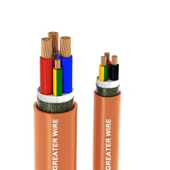
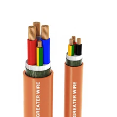

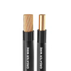
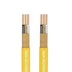
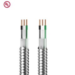
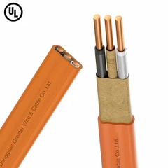
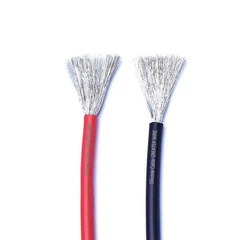
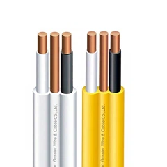
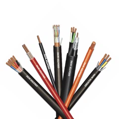
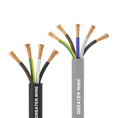
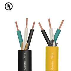
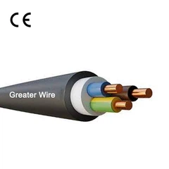

Selecting the correct conductor count for a TC-ER control cable is an important part of industrial electrical design. Too few conductors can leave a control circuit without the connections it needs, while too many can increase cable diameter, installation difficulty, and project cost.
For electrical contractors, panel builders, equipment manufacturers, and cable distributors, the right choice depends on more than the number of terminals in a control panel. You also need to consider the number of control circuits, signal types, grounding requirements, shielding, spare conductors, and the installation environment.
This guide explains how to select the conductor count for TC-ER control cable, how insulation types such as XHHW-2 Tray Cable and XHHW Cable fit into the specification, and when alternatives such as ITC or machine tool cable may be more appropriate.
1. Understand What Conductor Count Means in TC-ER Cable
TC-ER stands for Tray Cable–Exposed Run. It identifies a Type TC cable that has also been evaluated for specified exposed-run applications. In North America, UL 1277 covers electrical power and control tray cables, including products with two or more circuit conductors and optional grounding conductors.
The conductor count describes the number of insulated circuit conductors in the cable. It should not automatically be interpreted as the total number of conductive elements in the complete cable assembly.
For example, a cable may contain:
Four insulated circuit conductors.
One bare or insulated equipment grounding conductor.
An overall foil or braid shield.
A drain wire in contact with the shield.
These components perform different functions and should be identified separately in the cable specification.
What do 3/C, 4/C, and 5/C mean?
The abbreviation C usually means conductors. A 4/C cable, for example, contains four insulated conductors. Whether a grounding conductor is included depends on the product construction and how the manufacturer defines its configuration.
| Cable description | General meaning | Important point |
|---|---|---|
| 2/C | Two insulated circuit conductors | Often used for simple two-wire control circuits |
| 3/C | Three insulated circuit conductors | May serve three-wire control or other circuit arrangements |
| 4/C | Four insulated circuit conductors | Can accommodate additional control functions or power connections |
| 5/C | Five insulated circuit conductors | May support more complex control or power arrangements |
| 7/C | Seven insulated circuit conductors | Useful where several control connections share one cable |
| 12/C | Twelve insulated circuit conductors | Can consolidate multiple control circuits |
| 18/C or 20/C | Eighteen or twenty insulated circuit conductors | Often considered for equipment with numerous control points |
These are common cable-count descriptions, not a universal list of standard TC-ER configurations. Actual available counts depend on the cable manufacturer's product range, conductor size, insulation, and construction.
Important: Always confirm whether the quoted conductor count includes or excludes the equipment grounding conductor. Do not assume that a 4/C cable automatically contains four circuit conductors plus a ground.


2. Start by Counting the Required Control Connections
The most reliable way to select conductor count is to begin with the electrical schematic or wiring diagram.
Identify every connection that must run between the control panel and the field equipment. Then group the connections by function.
Typical industrial control connections include:
Start and stop push buttons.
Limit switches and proximity sensors.
Solenoid valves.
Relay coils and auxiliary contacts.
Motor starters and contactor control circuits.
Indicator lights and status signals.
Analog transmitters.
PLC digital inputs and outputs.
Interlocks and safety-related signals.
Each circuit may require one or more conductors depending on its electrical design.
For example, a two-wire device loop generally requires two conductors, while a three-wire sensor may require separate power, common, and signal connections. A four-wire transmitter may require a different arrangement depending on whether its power supply and signal circuits are isolated.
Do not count devices alone. Count the actual electrical connections shown on the approved wiring diagram.
Example: Selecting cable count for a simple control station
Suppose a remote control station has:
One start push button.
One stop push button.
One status indicator.
One additional control contact.
The number of conductors required depends on the control voltage, common-return arrangement, contact wiring, and circuit design.
A simplified connection schedule might look like this:
| Connection function | Required conductors |
|---|---|
| Start push-button circuit | 2 |
| Stop push-button circuit | 2 |
| Indicator circuit | 2 |
| Additional control contact | 2 |
| Total before design review | 8 |
This does not automatically mean an 8/C cable is the final answer. The engineer must check whether any circuits can share a common conductor under the approved design, whether separation is required, and whether the cable construction is suitable for all circuits.
The example illustrates why a wiring schedule is more reliable than choosing a cable count based only on the number of devices.
3. Decide Whether to Include Spare Conductors
Spare conductors can make future equipment modifications easier. They may allow an additional sensor, indicator, or control function to be connected without installing another cable.
However, there is no universal NEC rule requiring every TC-ER control cable to include a fixed percentage of spare conductors.
The number of spare conductors should be determined by the project design and expected expansion needs.
Consider including spare conductors when:
The equipment is likely to receive additional sensors or switches.
The machine design may be expanded later.
Replacing or installing another cable would be difficult.
The cable route is long or passes through congested trays.
The project specification requires spare cores.
For a small machine with a stable design, one spare conductor may be sufficient-or no spare may be necessary. A large automation system may justify more spare conductors or separate spare pairs.
How many spare conductors should you specify?
Use a practical design review rather than applying an arbitrary percentage.
| Project situation | Possible approach |
|---|---|
| Fixed equipment with no planned expansion | Specify only the conductors required by the approved schematic |
| Small machine with minor future modifications expected | Consider one or two spare conductors |
| Automated production line | Review likely sensor, actuator, and interlock additions |
| Large industrial installation | Consider separate spare pairs or dedicated expansion cables |
| Difficult cable replacement route | Evaluate additional spare capacity before installation |
These are planning examples, not code-mandated quantities. The final count should be approved by the electrical designer or project engineer.
Spare conductors should also be identified, insulated, and terminated or insulated safely according to the project and applicable installation requirements. They should not be left exposed or connected arbitrarily.

4. Count Grounding Conductors Separately
One of the most common specification mistakes is confusing insulated circuit conductors with the equipment grounding conductor (EGC).
An EGC provides a path for fault current and helps ensure that exposed conductive equipment parts are connected to the grounding system. It is not simply another spare control conductor.
For example, a cable may be specified as:
4 insulated circuit conductors plus 1 grounding conductor.
7 insulated circuit conductors plus 1 grounding conductor.
12 insulated circuit conductors with no integral grounding conductor.
The actual construction must be confirmed with the manufacturer.
Does every TC-ER control cable need an integral ground?
Not necessarily. UL 1277 covers Type TC cable constructions with or without grounding conductors. Whether an EGC is required, and how it is provided, depends on the circuit, equipment, installation method, and applicable electrical code.
When specifying a cable, identify:
The number of insulated circuit conductors.
Whether an integral EGC is required.
The grounding conductor material and size.
Whether the grounding conductor must be bare or insulated.
How the cable will connect to the equipment grounding system.
Do not assume that a cable shield or drain wire can replace an EGC. A shield is primarily intended to control electromagnetic interference, while the EGC serves a protective grounding function. Any alternative grounding arrangement must be specifically permitted by the applicable code and equipment instructions.
5. Consider Signal Types and Shielding Requirements
Conductor count alone does not determine whether a control cable is suitable for a particular signal.
A cable carrying low-voltage digital signals may have different requirements from one carrying analog instrumentation signals. The cable construction may need twisted pairs, individual pair shielding, an overall shield, or a combination of these features.
Common control signal requirements
| Signal or circuit type | Typical design considerations |
|---|---|
| 24 V DC digital input/output | Confirm conductor count, circuit grouping, and separation requirements |
| Push-button and limit-switch circuits | Count the actual contact and common connections |
| 4–20 mA analog signals | Consider twisted pairs and shielding where required |
| Thermocouple signals | Use appropriate thermocouple extension or compensation cable |
| Encoder signals | Check signal type, pair arrangement, shielding, and manufacturer requirements |
| Communication circuits | Use cable designed for the specific communication protocol |
| Relay and solenoid circuits | Check operating current, voltage drop, and interference concerns |
A cable with many conductors is not automatically suitable for sensitive instrumentation. For example, an unshielded 12/C cable may have enough conductors for several analog signals but may not provide the required signal integrity.
Overall shield or individually shielded pairs?
An overall shield surrounds all insulated conductors and can help reduce external electromagnetic interference.
Individually shielded pairs provide additional separation between signal pairs and can be useful where crosstalk or signal integrity is important.
Some cables combine individual pair shields with an overall shield.
The correct design depends on:
Signal type and frequency.
Electrical noise from nearby equipment.
Cable routing and separation.
Instrument and PLC manufacturer instructions.
Grounding and bonding design.
A drain wire, when included, provides a convenient electrical connection to the shield. It is not an additional signal conductor and should not be counted as one of the required circuit conductors.

6. Select the Right Insulation: XHHW, XHHW-2, and TC-ER
The insulation type is another important part of the cable specification.
XHHW Cable is a conductor insulation designation commonly used in North American wire and cable products. It is associated with cross-linked thermoset insulation and has specific temperature ratings.
However, XHHW and XHHW-2 do not have identical wet-location ratings.
| Conductor designation | Typical maximum temperature rating |
|---|---|
| XHHW | 90°C dry, 75°C wet |
| XHHW-2 | 90°C dry, 90°C wet |
Therefore, the keyword 90°C XHHW Cable needs to be used carefully. XHHW is generally rated 90°C in dry locations, but its typical wet-location rating is 75°C. XHHW-2 is rated 90°C in both dry and wet locations.
UL 44 covers thermoset-insulated wires and cables, including these conductor designations.
Does XHHW-2 automatically mean the complete cable is TC-ER?
No. This distinction is essential.
XHHW-2 identifies an insulated conductor type. TC-ER identifies the complete power and control tray cable product and its exposed-run evaluation.
A cable described as XHHW-2 Tray Cable should therefore be checked for both:
The conductor insulation designation and temperature rating.
The complete cable assembly's Type TC-ER listing and applicable markings.
The presence of XHHW-2 insulated conductors does not, by itself, establish that the finished cable is listed as TC-ER.
Also, a 90°C conductor insulation rating does not automatically mean that the circuit can use the 90°C ampacity at its equipment terminations. Terminal temperature limitations and applicable NEC requirements, including 110.14(C), must be considered.
7. TC-ER vs ITC Cable: Does Conductor Count Change the Choice?
Both TC-ER and ITC cables are used in industrial cable tray environments, but they are designed for different applications.
When comparing TC-ER vs ITC Cable, the main consideration should be the circuit function and applicable product standard-not simply the number of conductors.
| Feature | Type TC / TC-ER | Type ITC |
|---|---|---|
| Main application | Electrical power and control circuits | Instrumentation and related control circuits |
| Main UL standard | UL 1277 | UL 2250 |
| NEC article | Article 336 | Article 727 |
| Typical circuit scope | Power and control circuits within the product's ratings and installation permissions | Circuits rated 150 V or less and 5 A or less under the UL 2250 scope |
| Cable voltage rating | Many products are rated 600 V | Rated 300 V but not marked as such |
| Grounding conductor | Optional, depending on construction | Optional, depending on construction |
| Shielding | Depends on product construction | Depends on product construction |
UL 2250 covers Type ITC instrumentation cables intended for specified low-voltage, low-current circuits. A Type ITC cable should not be selected as a general substitute for a power or control cable outside its permitted application.
Similarly, a TC-ER cable is not automatically the best choice for every instrumentation circuit. Sensitive signals may require specific twisted-pair, shielding, or other performance characteristics.
The selection process should start with the circuit requirements and the applicable cable standard. Conductor count is only one part of the decision.
8. When Is Machine Tool Cable a Better Option?
Some industrial equipment uses cable identified as Machine Tool Cable or MTW. This term is associated with machine-tool wiring applications and should not be treated as another name for TC-ER.
For North American applications, MTW is covered by UL 1063. Its suitability depends on the actual product marking, applicable machine wiring requirements, and installation conditions.
A cable with an MTW marking is not automatically listed for cable tray or exposed-run installation. Likewise, a TC-ER cable is not automatically suitable for every machine-tool wiring application.
When selecting between these cable types, consider:
Whether the cable will be installed inside a machine or routed through a building cable tray.
Whether the application requires flexible machine wiring.
The cable's voltage and temperature ratings.
The required conductor count and grounding arrangement.
The relevant machine wiring standard and local electrical code.
Whether the cable is specifically listed for the proposed installation method.
For machinery with numerous control connections, a multi-conductor TC-ER cable may be appropriate for a permitted tray or exposed-run route. MTW may be more appropriate for certain internal machine wiring applications.
The product markings and machine manufacturer's wiring requirements should determine the final choice.


9. Check Oil Resistance and the Installation Environment
Industrial control cables may be installed near hydraulic systems, lubricated machinery, cutting fluids, or other substances that can affect cable materials.
If the installation requires an Oil Resistant Cable, check the actual oil-resistance marking rather than assuming that a particular insulation material or black outer jacket provides the required protection.
For applicable TC cable products, UL 1277 recognizes oil-resistance markings such as:
| Marking | General oil-resistance rating |
|---|---|
| Oil Resistant I / Oil Res I | Evaluated for exposure to oil at temperatures up to 60°C |
| Oil Resistant II / Oil Res II | Evaluated for exposure to oil at temperatures up to 75°C |
These ratings should be verified on the complete product and its documentation. The oil-resistance performance of the outer jacket and the insulated conductors may be identified separately.
Also consider other environmental requirements:
Wet-location suitability.
Sunlight and UV resistance.
Chemical compatibility.
Ambient temperature.
Flame performance.
Mechanical impact and abrasion.
Minimum bending radius.
A cable that is suitable for one type of industrial oil is not automatically compatible with every lubricant, coolant, solvent, or process chemical. Where chemical exposure is significant, request compatibility information from the cable manufacturer.
10. A Practical Method for Selecting TC-ER Control Cable Conductor Count
For project engineers and purchasing teams, the following process helps turn a wiring requirement into a clear cable specification.
Step 1: Identify the cable's function
Determine whether the cable carries digital control signals, analog instrumentation, relay circuits, power, or a combination of circuit types.
Do not combine circuits with incompatible electrical or installation requirements in one cable simply to reduce conductor count.
Step 2: Review the wiring diagram
List every required electrical connection between the control panel and the field equipment.
Record the number of conductors needed for each device and circuit.
Step 3: Determine the grounding arrangement
Decide whether the cable needs an integral equipment grounding conductor. Specify its size and construction separately from the insulated circuit conductor count.
Step 4: Decide whether shielding is necessary
Check signal sensitivity, nearby electrical noise, and equipment manufacturer requirements.
Specify overall shielding or individual pair shielding where needed. Identify the drain wire separately.
Step 5: Allow for future expansion
Review whether spare conductors are justified by planned equipment modifications, difficult cable routes, or project specifications.
Do not add unnecessary cores without considering the resulting cable diameter, weight, and installation cost.
Step 6: Confirm insulation and environmental requirements
Select the appropriate conductor insulation, jacket material, temperature rating, and environmental markings.
For example, confirm whether XHHW or XHHW-2 is required, and whether oil resistance or sunlight resistance is part of the project specification.
Step 7: Verify the complete cable listing
Confirm that the finished cable-not merely its individual insulated conductors-is listed and marked for the intended Type TC or TC-ER application.
Example cable specification worksheet
| Specification item | Example requirement |
|---|---|
| Cable type | Type TC-ER |
| Application | Industrial control wiring |
| Circuit function | Digital inputs and outputs |
| Insulated conductor count | 12 |
| Conductor size | To be determined from circuit requirements |
| Conductor material | Copper |
| Insulation | XHHW-2, if required and available in the listed construction |
| Grounding conductor | One insulated or bare EGC, as specified |
| Shielding | Overall foil shield with drain wire, if required |
| Jacket | Suitable for the installation environment |
| Oil resistance | Oil Res I or II, if required |
| Voltage rating | Confirm from the complete product marking |
| Certification | Applicable UL listing and any required destination-market approvals |
This is an example of how to organize a specification, not a universal cable design. The actual conductor size, number, grounding construction, and shield arrangement must be determined by the project engineer.
11. Common Mistakes When Specifying TC-ER Control Cable
Mistake 1: Counting devices instead of electrical connections
One device may require two, three, or more conductors depending on its wiring arrangement. Use the schematic rather than the equipment quantity.
Mistake 2: Counting the grounding conductor as a spare core
The EGC has a protective function. It should be specified separately and should not be treated as an unused signal conductor.
Mistake 3: Assuming more conductors always mean a better cable
A larger conductor count can increase cable diameter, weight, bending requirements, and installation complexity. Select only the capacity justified by the circuit design and reasonable future needs.
Mistake 4: Treating XHHW and XHHW-2 as interchangeable
XHHW has a typical 75°C wet rating, while XHHW-2 is rated 90°C wet and dry. Confirm the exact conductor designation.
Mistake 5: Assuming every TC-ER cable is shielded
Shielding is a construction option, not an automatic feature of the TC-ER designation. Specify the shield type and coverage where required.
Mistake 6: Assuming oil resistance from the jacket material
Oil resistance must be confirmed from the product's applicable marking and technical documentation. A PVC or other polymer jacket does not automatically establish an Oil Res I or Oil Res II rating.
Mistake 7: Confusing TC-ER with ITC or MTW
These cable types have different product standards and intended applications. Verify the required listing and wiring method before choosing a substitute.
Conclusion
Selecting the correct TC-ER control cable conductor count starts with the wiring diagram and the actual electrical connections. Engineers and buyers should count insulated circuit conductors, specify the equipment grounding conductor separately, evaluate shielding and signal requirements, and decide whether spare conductors are justified.
Insulation and environmental ratings are equally important. A cable using XHHW-2 conductors must still have the appropriate complete cable listing, while oil resistance and other environmental properties must be verified from the product markings.
The best specification is not necessarily the cable with the most conductors. It is the cable whose conductor count, grounding arrangement, insulation, shielding, and certifications match the application without adding unnecessary installation cost.
Discuss Your TC-ER Control Cable Requirements with GERITEL WIRE
Choosing the right conductor count is essential for reliable industrial control wiring and efficient installation. GERITEL WIRE works with electrical distributors, contractors, panel builders, and equipment manufacturers to discuss cable requirements for a range of industrial applications. Whether your project calls for XHHW-2 Tray Cable, multi-conductor control cable, shielded construction, or an Oil Resistant Cable, share your conductor count, wire size, grounding, shielding, and environmental requirements with our team. Contact GERITEL WIRE to discuss your specifications and explore a suitable cable configuration for your next project.
Dongguan Greater Wire & Cable Co., Ltd.
Tel/WhatsApp/Wechat: +86 136 6257 9592
Tel/WhatsApp/Wechat: +86 135 1078 4550
Email: manager01@greaterwire.com
Website: www.greaterwire.com