1. Why is ampacity calculation necessary?
Selecting the appropriate wire size and protection is crucial in electrical system design. Correctly calculating ampacity ensures that wires do not overheat or overload under the expected load, while also achieving a balance between safety and cost-effectiveness. THHN wire (Thermoplastic High Heat-resistant Nylon-coated) is widely used in construction and industry due to its structural and heat-resistant properties, making accurate assessment of its ampacity crucial.

2. Basic Concepts and Terminology
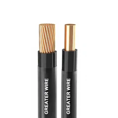
THHN wire: Contains copper or aluminum conductors, thermoplastic insulation, and a nylon jacket. It is rated for operating temperatures up to 90°C and suitable for use in both dry and humid environments.
Ampacity: The maximum current a conductor can safely carry for an extended period under specific conditions, a critical parameter in engineering applications.
NEC: The U.S. National Electrical Code serves as the key legal basis for selecting THHN wire.
3. Related Standards and Regulations
NEC Table 310.15(B)(16) lists the basic current carrying capacity (I_table) of different conductor sizes at different temperature ratings. For example, according to this table, the current carrying capacity of 6 AWG THHN copper conductor at 90°C is 75A; 8AWG is 55A.
NEC 110.14(C) states that although a conductor may have a higher temperature rating, actual use may require it to be limited to a lower temperature rating due to terminal or connection point temperature limitations. Data for the higher temperature rating should only be used when performing derating calculations.

4. Theoretical Basis for Ampacity Calculation
The commonly used basic formula for ampacity calculation is as follows:
I_actual = I_table × C_temp × C_group
I_table: Base ampacity value from the NEC table.
C_temp (Temperature Correction Factor): Corrects for ambient temperature deviations from the baseline (usually 30°C). For example, at 40°C, the temperature factor for a 90°C-rated conductor is approximately 0.91.
C_group (Bundling Correction Factor): When the number of conductors exceeds three, heat dissipation performance degrades, requiring further correction. For 4–6 conductors, the corresponding factor is 0.80, for 7–9 conductors, 0.70, and so on.
Continuous Load: The NEC requires a 125% margin for continuous load. Therefore, the circuit breaker capacity should be at least 125% of the actual load, and the conductor's allowable ampacity should be adjusted accordingly.
5. Detailed Calculation Steps
1.Check the Basic Ampacity (I_table)
For example: 6 AWG copper THHN has a current rating of 75A at 90°C, while 8 AWG has a current rating of 55A.
2.Apply the Temperature Correction Factor (C_temp)
If the ambient temperature is 40°C, the correction factor for 90°C-rated THHN is approximately 0.91.
3.Apply the Bundling Correction Factor (C_group)
If four conductors are arranged in a conduit, use a correction factor of 0.80.
4.Calculate the Actual Allowable Ampacity
Using 8 AWG as an example:
I_actual = 55A × 0.91 × 0.70 ≈ 35A.
If the load is 39A, it is not sufficient and needs to be upgraded to Thhn 6 AWG. The calculated current is 48A, which is acceptable.
5.Continuous Load Handling
For continuous load (≥3 hours), multiply the load by 1.25 and then calculate the difference. Comparison of I_actual ensures safety design requirements are met.
6.Terminal temperature rating comparison
Although the conductor allows for 90°C data, terminal limitations may ultimately limit it to 75°C or 60°C, depending on the specific device terminal temperature rating.
6. Case Study Demonstration
Case 1: Single Conductor in a 40°C Environment
Conductor: 6 AWG Copper THHN
Table Reference: Base Current Capacity: 75A
Temperature Correction: 0.91 → 75 × 0.91 = 68.25A
Bundling Correction: Single conductor, no derating → 68.25A
Continuous Load Consideration: If the load is 60A, the required current is: 60 × 1.25 = 75A → 68.25A. This is not sufficient, so upgrading the specifications is recommended.
Case 2: Four conductors in conduit
Conductor: 8 AWG copper THHN
Base current carrying capacity: 55A
Temperature correction: 0.91 → 55 × 0.91 ≈ 50A
Bundling correction (4 conductors): 0.80 → 50 × 0.80 = 40A
Continuous load: Assuming a 30A load → 30 × 1.25 = 37.5A < 40A → Acceptable

