

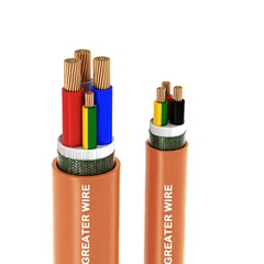
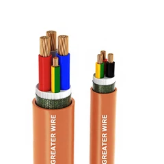

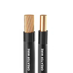
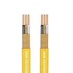
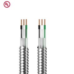
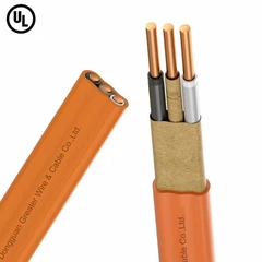
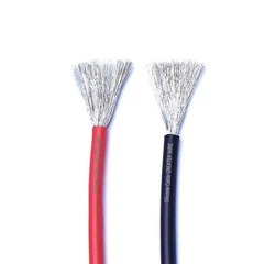
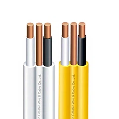

In industrial electrical systems, electrical noise can interfere with control signals, instrumentation, communication links, and sensitive automation equipment. Choosing the right shield for a tray cable can help reduce this risk, but foil and braid shields work differently. The better option depends on the interference frequency, grounding and termination method, mechanical conditions, cable construction, and project requirements.
For electrical distributors, contractors, OEMs, and procurement teams, selecting Tray Cable UL1277 involves more than comparing shield materials. Buyers must also confirm the cable's listing, conductor and insulation specifications, jacket ratings, and permitted installation methods.
1. What Is the Difference Between Foil Shield and Braid Shield?
A cable shield is a conductive layer placed around individual conductors, twisted pairs, or the assembled cable core. Its purpose is to reduce electromagnetic interference (EMI) and, depending on the design and installation, limit unwanted electrical coupling into or out of the cable.
Foil and braid shields are common options in industrial power and control cables. Their main differences are construction, coverage, electrical resistance, mechanical characteristics, and termination requirements.
Foil Shield: High Coverage with Low Added Weight
A foil shield typically consists of a thin metal layer, commonly aluminum, bonded to a polyester or other supporting film. The foil may surround individual pairs or the entire cable core.
Its main advantages include:
High physical coverage: A properly applied foil layer can provide nearly continuous, nominally 100% coverage, reducing gaps through which high-frequency electric-field interference may couple.
Low weight and compact construction: Foil generally adds less weight and bulk than a comparable copper braid.
Cost-effective shielding: It can be a practical choice for instrumentation, control, and signal circuits where high coverage is important.
Drain-wire termination: Many foil-shielded designs include a drain wire to provide a convenient electrical connection to the shield.
However, the metal layer is thin and can be more vulnerable to damage during repeated bending or rough handling. The foil itself may also be difficult to terminate reliably without a suitable drain wire or designed termination system.
A foil shield does not automatically provide effective protection against every type of interference. Its performance depends on frequency, shield construction, grounding, cable routing, and the quality of the installation.
Braid Shield: Lower Resistance and Greater Mechanical Strength
A braid shield consists of interwoven metal strands, commonly bare or tinned copper, arranged around the cable core. Its coverage depends on factors such as wire diameter, braid angle, and weave density.
Its main advantages include:
Lower electrical resistance: A copper braid typically offers a lower-resistance path than a thin aluminum foil shield, which can be beneficial for controlling certain interference currents.
Mechanical robustness: The woven structure generally withstands handling and some mechanical stresses better than a thin foil layer alone.
Practical termination: A braid can often be connected directly to a suitable shield clamp, gland, or bonding arrangement.
Good shielding versatility: A properly designed braid can be effective across a useful range of frequencies, including applications where low shield resistance matters.
The limitations are equally important. A braid has small openings between its strands, so it does not provide the continuous geometric coverage of a foil layer. It is also typically heavier and may increase cable diameter and cost.
Braid construction alone does not guarantee superior shielding. Coverage percentage, braid material, transfer impedance, frequency range, and termination quality all influence performance.

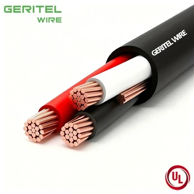
2. Foil Shield vs Braid Shield: Key Differences at a Glance
| Selection factor | Foil shield | Braid shield |
|---|---|---|
| Construction | Thin metal foil bonded to a supporting film | Interwoven conductive metal strands |
| Typical coverage | Near-continuous, often specified as 100% nominal coverage | Incomplete coverage; depends on braid design |
| High-frequency electric-field interference | Often advantageous because of continuous coverage | Can be effective, depending on coverage and construction |
| Low-frequency magnetic interference | Thin foil alone may provide limited attenuation | May perform better when low resistance and suitable bonding are provided |
| Electrical resistance | Generally higher than a comparable copper braid | Generally lower with a suitably sized copper braid |
| Mechanical durability | Foil can be vulnerable to tearing or repeated flexing | Usually more mechanically robust |
| Termination | Often uses a drain wire or designed shield connection | Often permits direct connection through a clamp or other termination |
| Weight and cable diameter | Typically lower | Typically higher |
| Relative cost | Often lower | Often higher |
| Best selection basis | Continuous coverage, weight, and cost priorities | Lower resistance, mechanical robustness, and termination needs |
These are general tendencies, not guaranteed performance ratings. A thick, carefully designed foil shield may outperform a poorly constructed braid in a particular application, and a suitable braid may outperform foil under different conditions. Compare manufacturer test data and the actual cable construction rather than relying on the shield name alone.
3. Which Shield Is Better for Tray Cable Applications?
The correct choice depends on the type of circuit, the surrounding electrical environment, and the required level of noise control.
When Foil Shield Is a Good Choice
Consider foil-shielded tray cable when:
Instrumentation or control signals are sensitive to high-frequency electrical interference.
High shield coverage is a priority.
Cable weight and overall diameter must be controlled.
The installation can accommodate the required drain-wire connection and grounding arrangement.
The expected mechanical conditions are compatible with the cable's construction and permitted bending radius.
For example, an industrial monitoring system may use foil-shielded cable to help reduce unwanted coupling into low-level signals. The actual benefit will still depend on signal type, installation layout, and the shield's connection to the system grounding design.
When Braid Shield Is a Good Choice
Consider braid-shielded tray cable when:
Lower shield resistance is important.
The application requires a mechanically robust shield.
Shield termination and bonding must be straightforward.
The electrical environment includes interference that a suitably designed braid can help control.
The additional weight, diameter, and cost are acceptable.
Braid shielding may be suitable for certain motor-control and industrial control circuits, but a standard braid is not automatically adequate for every variable-frequency drive (VFD) installation. VFD applications can require a purpose-designed cable with specified shield coverage, grounding conductors, symmetrical conductor arrangements, and termination methods.
When a Combined Foil-and-Braid Shield Makes Sense
In demanding environments, a combined foil-and-braid shield can provide the advantages of both structures: the foil contributes high coverage, while the braid offers a lower-resistance conductive layer and additional mechanical strength.
This option may be worth evaluating when a cable runs near drives, switching power equipment, or other significant noise sources, particularly when sensitive signals must remain reliable.
However, a dual shield is not always necessary. It can increase cable diameter, weight, cost, and termination complexity. Confirm the required shielding performance and installation method before specifying it.

4. How to Select Shielding for a UL 1277 Tray Cable
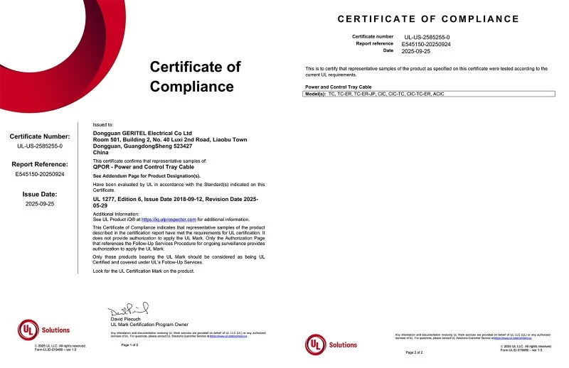
The UL1277 Cable Standard covers electrical power and control tray cables, including specified constructions with optional optical-fiber members. It addresses the cable within its applicable product and installation framework; choosing foil or braid does not, by itself, establish compliance or authorize a particular installation.
For US projects, UL 1277 and the applicable National Electrical Code (NEC) requirements should be reviewed alongside the exact product listing and markings. For Canadian or other international projects, verify the relevant Canadian certification or local standards separately. A UL marking should not be assumed to establish CSA or IEC compliance.
Use the following checks when comparing supplier quotations.
Check 1: Confirm the Required Electrical Performance
Identify whether the cable carries power, analog instrumentation signals, digital control signals, or VFD output. Determine the expected noise sources and relevant frequency range.
Where interference control is critical, ask for applicable shielding data, such as braid coverage, shield resistance, transfer impedance, or measured attenuation under defined test conditions. A statement such as "foil shield" or "85% braid" alone may not provide enough information to evaluate the cable.
Check 2: Review Conductor and Insulation Specifications
Confirm conductor material, conductor size, number of cores, insulation type, voltage rating, and temperature rating.
For example, XHHW vs THHN Tray Cable is a separate specification question from foil versus braid shielding. XHHW-2 and THHN/THWN-2 have different insulation and use-related characteristics under their applicable standards. Their suitability depends on the actual cable construction, markings, environmental conditions, and installation rules. Do not assume that choosing one insulation type determines the required shield or guarantees a particular tray-cable listing.
Check 3: Evaluate the Outer Jacket and Environment
The jacket must suit the installation environment, including temperature, moisture, sunlight exposure, oils, chemicals, and mechanical risks where applicable.
A PVC Jacket Tray Cable may be appropriate for many industrial applications when its specific compound and finished-cable ratings meet the project requirements. PVC is not a universal guarantee of oil resistance, chemical compatibility, low-temperature performance, or outdoor suitability. Verify the actual product markings and manufacturer data.
If the cable will be installed outdoors, confirm any required sunlight-resistance rating. If it will be exposed to oil or chemicals, check the specified resistance claims against the actual substances and operating conditions.
Check 4: Confirm Core Count and Grounding Requirements
A 3 Conductor Tray Cable can be suitable for particular power or control circuits, but the required conductor count depends on the circuit design. Determine whether a protective grounding conductor, dedicated signal reference, or other conductor is needed.
The shield must not automatically be treated as a protective grounding conductor. A cable's shield and its equipment grounding conductor serve different functions unless a specific design and applicable rules explicitly establish otherwise.
Also verify whether the shield is intended to be bonded at one end, both ends, or through another engineered arrangement. The correct method depends on the circuit, equipment instructions, grounding design, and potential for ground-loop currents. Do not apply a universal grounding rule to every shielded cable.
Check 5: Verify the Finished Cable's Listing and Markings
Confirm the exact manufacturer, cable type, voltage and temperature ratings, environmental markings, and applicable certification records. Check that the product's listed construction covers the proposed application.
A shield option shown in a general catalogue does not necessarily mean every shielded configuration has the same certification status. Ask the supplier to confirm the actual cable model and its documentation.
5. Can a Shielded Tray Cable Be Used for Direct Burial?
Not automatically. Shielding and burial suitability are separate characteristics.
A foil shield or braid shield primarily addresses electrical interference and, in some designs, contributes to mechanical robustness. Neither feature by itself makes a cable suitable for direct burial.
A Direct Burial Cable must have the required construction, markings, and ratings for the intended burial conditions and comply with the applicable installation rules. For a US installation, check the cable's specific listing and NEC requirements, including any applicable provisions for direct-buried cable and the installation environment. Do not infer burial suitability from a UL 1277 reference alone.
Before purchasing cable for underground installation, verify:
Whether the exact product is identified and rated for direct burial.
Whether additional conduit, mechanical protection, or other measures are required.
Whether the cable is suitable for the site's moisture, soil, chemical, and temperature conditions.
Whether the shield, grounding conductors, and terminations meet the electrical design.
Whether the product's certification and installation permissions apply in the project jurisdiction.
These checks are especially important when comparing products described as "tray cable," "outdoor cable," or "direct-burial tray cable." Marketing descriptions are not substitutes for product-specific ratings and code requirements.
6. Common Purchasing Mistakes to Avoid
Mistake 1: Assuming 100% Coverage Means Better Performance in Every Situation
Foil offers continuous nominal coverage, but shielding effectiveness also depends on conductivity, shield thickness, frequency, bonding, and installation. Braid may be more suitable when lower shield resistance or mechanical robustness is more important.
Mistake 2: Selecting by Shield Type Without Defining the Circuit
A power circuit, low-level analog signal, communication link, and VFD output do not necessarily need the same cable construction. Define the circuit and noise environment before choosing a shield.
Mistake 3: Treating the Shield as Armor or a Grounding Conductor
A foil or braid shield is not automatically equivalent to metallic armor or a protective grounding conductor. Verify the cable construction and the applicable electrical requirements.
Mistake 4: Assuming All Shielded Cables Meet the Same Standard
The presence of a foil or braid does not prove that a finished cable is listed to UL 1277 or certified for another market. Confirm the exact model and certification scope.
Mistake 5: Overlooking Installation and Termination Details
Poor shield termination, unsuitable cable routing, or incorrect bonding can undermine the benefit of a well-designed shield. Follow the equipment manufacturer's instructions and the project's grounding and EMC requirements.
7. A Practical Decision Guide for Buyers
Use this simplified guide to narrow the options before requesting quotations.
| Project priority | Option to evaluate first | Important qualification |
|---|---|---|
| High coverage and compact construction | Foil shield | Check drain-wire design and termination |
| Lower shield resistance | Copper braid | Confirm braid coverage and electrical data |
| High coverage plus mechanical robustness | Combined foil and braid | Evaluate added cost, diameter, and termination needs |
| Demanding VFD environment | Purpose-designed VFD cable | Check shield, grounding, conductor arrangement, and drive requirements |
| Underground installation | Specifically rated direct-burial construction | Shield type alone does not establish burial suitability |
| General industrial tray installation | Product listed and marked for the intended use | Verify code, environmental ratings, and certification |
For high-consequence or noise-sensitive systems, request product-specific technical data rather than relying solely on this general guide. If possible, involve the electrical designer or EMC specialist in evaluating the cable and its termination method.
Conclusion: Choose the Shield Around the Application
Foil and braid shields solve related but different engineering problems. Foil is attractive when high coverage, low weight, and compact construction are priorities. Braid is worth considering when low shield resistance, termination convenience, and mechanical robustness matter. A combined shield can be justified when the installation demands both high coverage and a more substantial conductive layer.
The best Tray Cable UL1277 selection must also meet the project's conductor, insulation, jacket, voltage, environmental, certification, and installation requirements. Confirm the complete cable specification-not just the shielding type-before approving a purchase.

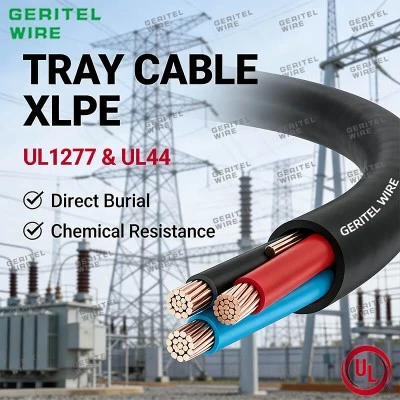
Explore Shielded Tray Cable Options with GERITEL WIRE
GERITEL WIRE supports industrial cable buyers in evaluating power and control cable specifications for their intended applications. When comparing foil-shielded, braid-shielded, or combined-shield constructions, our team can help clarify the information needed for a product inquiry, including conductor count and size, insulation material, jacket requirements, voltage rating, shielding design, and applicable market standards. Whether your project involves control panels, industrial equipment, or cable-tray installations, sharing your technical requirements helps establish a clearer basis for product selection and quotation. Contact GERITEL WIRE to discuss your project specifications and explore suitable cable options for your target market.
Dongguan Greater Wire & Cable Co., Ltd.
Tel/WhatsApp/Wechat: +86 136 6257 9592
Tel/WhatsApp/Wechat: +86 135 1078 4550
Email: manager01@greaterwire.com
Website: www.greaterwire.com