


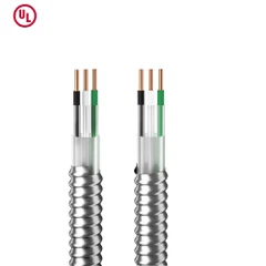
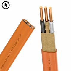

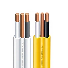
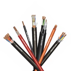
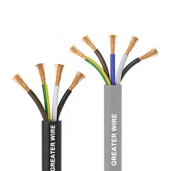
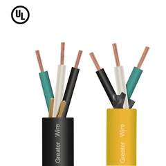
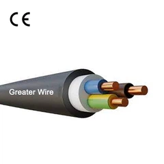
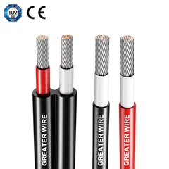


Voltage drop is an important consideration when selecting and sizing industrial power and control cables. In a long cable run, electrical resistance causes the voltage at the load to be lower than the voltage supplied by the source. If the drop is excessive, motors may experience reduced starting torque, equipment may operate outside its specified voltage range, and system performance may suffer.
For engineers, electrical contractors, and industrial procurement teams, calculating voltage drop in a TC-ER cable run helps determine whether the proposed conductor size and cable length are suitable for the application.
The calculation depends on the electrical system, load current, conductor resistance or impedance, and one-way cable length-not simply on the cable's TC-ER designation. This guide explains the formulas, a practical calculation example, and the key checks required before specifying a cable for an industrial project.
1.What Is TC-ER Cable, and Why Does Voltage Drop Matter?
What is TC-ER Cable?
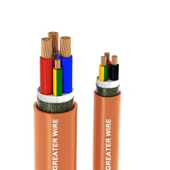
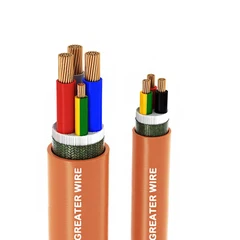
What is TC-ER Cable? TC-ER stands for Tray Cable–Exposed Run. It is a designation used in the North American electrical market for qualifying power and control tray cables permitted to be installed in certain exposed-run applications under applicable electrical code requirements.
In the United States, UL 1277 covers electrical power and control tray cables. The exposed-run designation is associated with additional mechanical performance requirements. Actual installation permissions depend on the cable's listing and markings, the applicable edition of the National Electrical Code (NEC), and the installation conditions.
Many TC-ER products are rated for 600 V, but buyers should verify the specific product's voltage rating, conductor insulation, temperature ratings, and environmental markings rather than assume every cable has identical specifications.
Voltage drop matters because a cable must deliver an appropriate voltage to the connected equipment under its expected operating load. A cable can satisfy the required voltage rating and still be too small for a particular run.


What Determines Voltage Drop in a TC-ER Cable Run?
Five factors are especially important:
Load current: Higher current generally produces a greater voltage drop.
Conductor size: Larger conductors generally have lower resistance and reduce voltage drop.
Cable length: Longer runs create more conductor resistance.
Conductor material: Copper and aluminum have different electrical resistance characteristics.
Electrical system and operating conditions: Phase configuration, power factor, conductor temperature, and AC impedance affect the calculation.
Cable construction and installation conditions also matter when selecting the final product. For example, a cable suitable for a fixed exposed run is not automatically suitable for continuous flexing, direct burial, or a hazardous location.
2. Which Voltage Drop Formula Should You Use?
The appropriate formula depends on whether the circuit is DC, single-phase AC, or three-phase AC. A simplified resistance-based formula is useful for preliminary sizing, while an impedance-based calculation is generally more appropriate for a detailed AC design.
DC and Single-Phase Circuits
For a DC circuit or a single-phase circuit using a resistance-based approximation:
[V_d=\frac{2KIL}{CM}]
Where:
(V_d) = voltage drop in volts
(K) = conductor resistance constant, commonly expressed in ohm-circular-mils per foot
(I) = load current in amperes
(L) = one-way cable length in feet
(CM) = conductor cross-sectional area in circular mils
The factor of 2 accounts for the outgoing and return conductors.
Three-Phase AC Circuits
For a balanced three-phase circuit using the same simplified method:
[V_d=\frac{\sqrt{3}KIL}{CM}]
The factor (\sqrt{3}), approximately 1.732, reflects the relationship between line voltage and phase quantities in a balanced three-phase system.
For preliminary calculations using common 75°C resistance-based constants, typical values are approximately:
Copper: (K=12.9)
Aluminum: (K=21.2)
These are approximate design constants, not universal cable specifications. They are associated with traditional AWG circular-mil calculations and should not replace manufacturer data or a more detailed impedance calculation where accuracy is important.
Calculating Percentage Voltage Drop
After calculating the voltage drop in volts, convert it into a percentage of the source voltage:
[%V_d=\frac{V_d}{V_s}\times100]
Where (V_s) is the nominal circuit voltage.
For example, a 6 V drop in a 480 V circuit equals:
[\frac{6}{480}\times100=1.25%]
The percentage helps engineers compare circuits operating at different voltage levels.

When Should You Use AC Impedance Instead of Resistance?
For AC circuits, resistance alone may not fully represent the voltage drop. Conductor reactance, power factor, conductor arrangement, and operating temperature can also affect the result.
For a balanced three-phase circuit, a commonly used approximation is:
[V_d=\sqrt{3}IL(R\cos\phi+X\sin\phi)]
Here, (R) and (X) are the conductor resistance and reactance per unit length, (L) is the one-way length expressed in the same length unit, and (\phi) is the load power-factor angle. The resistance and reactance values must use consistent units and reflect suitable operating conditions.
For single-phase AC circuits, the corresponding approximate expression is:
[V_d=2IL(R\cos\phi+X\sin\phi)]
These expressions assume a suitable simplified circuit model. For a detailed design, use the applicable engineering method and reliable cable impedance data. Do not mix resistance values expressed per 1,000 feet with cable lengths expressed in metres without converting the units.

3. Step-by-Step Example: Calculating Voltage Drop in a TC-ER Cable Run
Consider a hypothetical industrial installation with the following parameters.
| Parameter | Example value |
|---|---|
| Cable type | Copper-conductor TC-ER |
| Electrical system | 480 V, three-phase AC |
| Load current | 30 A |
| One-way cable length | 200 ft |
| Conductor size | 10 AWG copper |
| Calculation method | Simplified resistance-based method |
| Copper constant, (K) | 12.9 |
This example illustrates the calculation process. It is not a recommendation to use 10 AWG for every 30 A circuit; final conductor selection must also account for ampacity, terminal temperature ratings, applicable code requirements, and installation conditions.
Step 1: Identify the Circuit Parameters
Confirm the source voltage, phase configuration, expected load current, and one-way distance from the source to the load.
The 200 ft figure represents the one-way route length, not the combined length of all conductors. The simplified three-phase formula already incorporates the appropriate (\sqrt{3}) factor.
Step 2: Determine the Conductor Area
The approximate cross-sectional area of 10 AWG copper is 10,380 circular mils.
Therefore:
[CM=10{,}380]
For a real project, verify the conductor size and construction against the cable manufacturer's datasheet.
Step 3: Calculate the Voltage Drop
Substitute the values into the three-phase formula:
[V_d=\frac{1.732\times12.9\times30\times200}{10{,}380}]
The calculated voltage drop is approximately:
[V_d\approx12.9\text{ V}]
This result is an estimate based on the simplified resistance method. A final AC calculation may produce a different result when conductor temperature, reactance, and power factor are included.
Step 4: Calculate the Percentage Drop
The source voltage is 480 V:
[%V_d=\frac{12.9}{480}\times100]
[%V_d\approx2.69%]
The estimated voltage drop is therefore approximately 2.69%.
Step 5: Evaluate the Result
The next step is to compare the calculated drop with the project's design criteria, equipment voltage requirements, and applicable electrical code provisions.
For context, the NEC commonly recommends limiting voltage drop to 3% for a branch circuit and 3% for a feeder, with a combined 5% recommendation for feeder and branch circuits supplying power to utilization equipment. These are recommendations in the relevant NEC provisions, not a universal statutory maximum for every circuit.
In this example, the simplified calculation is below 3%, but the designer should not approve the cable on that basis alone. The final check must include ampacity, starting current where relevant, actual conductor impedance, installation conditions, and equipment requirements.
4. How to Reduce Voltage Drop in a TC-ER Cable Run
If the calculated voltage drop exceeds the design target, consider the following measures.
Increase the Conductor Size
Using a larger conductor generally reduces resistance and voltage drop. For example, moving from 10 AWG to 8 AWG copper can improve the voltage-drop result, although the actual reduction should be calculated using the appropriate resistance or impedance data.
The selected conductor must also fit the cable construction, terminals, connectors, and installation requirements.
Shorten the Cable Route
Where the project layout allows, reducing the distance between the power source and load can reduce voltage drop without changing the conductor size.
However, the route should still provide appropriate mechanical protection, support, accessibility, and separation from other services.
Check the Actual Load Current
Calculations should reflect the expected operating current, not just the nominal equipment rating. Motors, for example, may draw significantly higher current during startup than during normal operation.
For equipment with substantial starting current or varying loads, consider both steady-state and transient voltage performance where required.
Use Manufacturer-Specific Electrical Data
Generic resistance constants are useful for preliminary estimates, but manufacturer data is preferable when finalizing a cable specification.
Confirm the conductor material, resistance at the relevant temperature, conductor size, and available AC impedance data. Also check whether the proposed cable is appropriate for the installation environment.


5. TC-ER Cable Selection: What Else Should Buyers Check?
Voltage drop is only one part of cable selection. A technically suitable cable must also meet the project's electrical, mechanical, environmental, and regulatory requirements.
TC-ER Cable vs Tray Cable
The distinction is primarily about installation permissions. TC refers to tray cable, while the ER designation identifies qualifying products intended for certain exposed-run applications under applicable code conditions.
Not every tray cable qualifies for exposed-run installation. Buyers should confirm the exact listing, markings, and permitted use rather than relying on appearance or a generic product description.
TC-ER vs ITC Cable
ITC means Instrumentation Tray Cable and is generally associated with instrumentation circuits. TC-ER power and control cables serve different circuit needs, although some products and applications may overlap depending on their ratings and approvals.
The right choice depends on the circuit function, conductor configuration, electrical characteristics, installation environment, and applicable code requirements. Do not substitute ITC for a power cable-or the reverse-without verifying suitability.
Industrial Tray Cable for Different Operating Environments
When selecting Industrial Tray Cable, buyers should review more than conductor size and voltage drop. Relevant considerations may include:
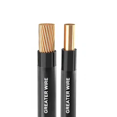
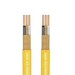
Conductor material, gauge, and strand construction
Insulation and overall jacket materials
Voltage and temperature ratings
Oil, sunlight, moisture, and chemical resistance where required
Flame-test ratings and certification marks
Mechanical protection, support, and minimum bending radius
Suitability for fixed installation or continuous flexing
A cable's environmental or flame-resistance properties should be confirmed from its actual markings and documentation. These characteristics should not be assumed to be included in every TC-ER product.
Is TC-ER Cable for Mining Industry Applications Suitable?
Mining environments can involve abrasion, impact, vibration, moisture, chemicals, and challenging installation conditions. A TC-ER designation alone does not establish that a cable is suitable for every mining application.
Before specifying TC-ER Cable for Mining Industry projects, evaluate the actual operating environment, mechanical protection requirements, applicable mining and hazardous-location rules, and any required approvals. Applications involving mobile equipment, continuous flexing, direct burial, or potentially explosive atmospheres may require a different cable construction or additional certification.
Working With a Custom TC-ER Cable Manufacturer
For OEMs, system integrators, and industrial project buyers, a Custom TC-ER Cable Manufacturer may help configure conductor sizes, core counts, grounding conductors, insulation, jackets, and other construction details to meet project needs.
Customization does not automatically confer a certification or installation approval. The finished cable must carry the appropriate listing and markings for its intended application, and its electrical performance must be evaluated using the actual product specifications.
6. Voltage Drop Calculation Checklist for Industrial Buyers
Before approving a TC-ER cable run, confirm the following information with the project engineer or cable supplier.
| Check | Information to confirm |
|---|---|
| Supply | Nominal voltage and AC/DC system |
| Phase | Single-phase or three-phase |
| Load | Expected operating current and power factor |
| Route | One-way cable length |
| Conductor | Copper or aluminum; AWG or mm² size |
| Electrical data | Resistance or impedance at relevant conditions |
| Installation | Tray, exposed run, raceway, or other permitted method |
| Environment | Temperature, moisture, sunlight, oil, chemicals, and mechanical exposure |
| Compliance | Applicable code, cable listing, and required approvals |
| Final verification | Voltage drop, ampacity, terminals, and equipment requirements |
This checklist helps prevent a common procurement mistake: choosing a cable based only on nominal voltage or conductor size without checking its suitability for the complete installation.
Conclusion
Calculating voltage drop in a TC-ER cable run requires the correct circuit formula, load current, one-way length, conductor size, and electrical resistance or impedance data. A simplified resistance-based method is useful for preliminary estimates, but final AC designs may require additional consideration of power factor, reactance, and conductor temperature.
For B2B buyers, the most reliable selection process combines voltage-drop calculations with ampacity checks, equipment requirements, installation permissions, and verification of the finished cable's ratings and certifications. This approach helps ensure that the selected cable is electrically appropriate and suitable for the intended industrial application.
GERITEL WIRE: TC-ER Cable Solutions for Industrial Projects
GERITEL WIRE supports industrial buyers, equipment manufacturers, and electrical contractors seeking cable solutions tailored to their project requirements. Whether you need a standard TC-ER configuration or are evaluating a customized cable for a particular installation, our team can help you review conductor sizes, core configurations, insulation and jacket options, and relevant technical documentation. Share your operating voltage, load current, cable length, installation environment, and required approvals so that your project requirements can be evaluated more efficiently. Contact GERITEL WIRE to discuss your cable specifications, request product information, and explore a suitable solution for your next industrial project.
Dongguan Greater Wire & Cable Co., Ltd.
Tel/WhatsApp/Wechat: +86 136 6257 9592
Tel/WhatsApp/Wechat: +86 135 1078 4550
Email: manager01@greaterwire.com
Website: www.greaterwire.com