

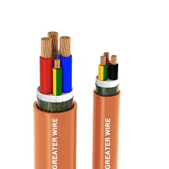
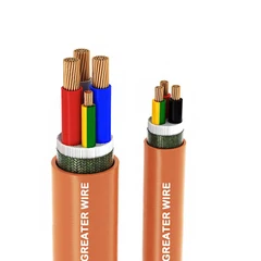


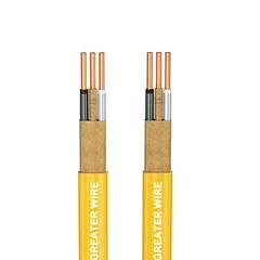
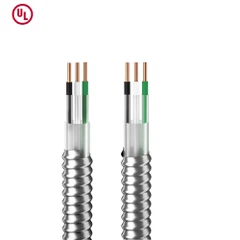



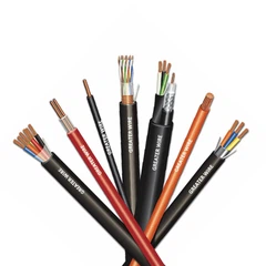
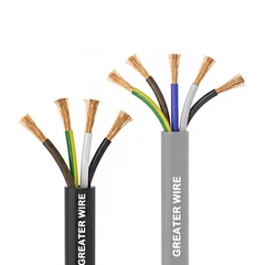
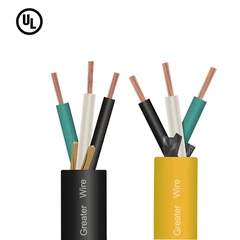
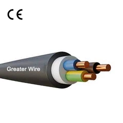
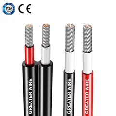

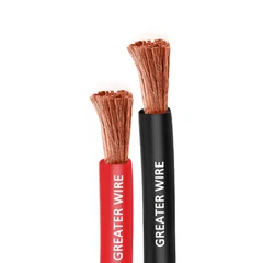
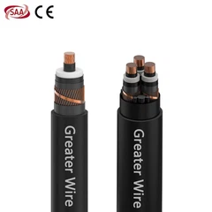
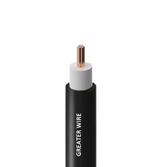

Cable tray fill is an important consideration when planning industrial electrical installations. An overloaded tray can make cable installation more difficult, restrict space for future expansion, and create challenges for cable support, heat dissipation, and maintenance. For electrical contractors, engineers, OEMs, and procurement teams, calculating cable tray fill before installation helps ensure that the selected tray can accommodate the planned cable configuration.
However, there is no single fill percentage that applies to every TC-ER cable installation. The permitted cable quantity depends on the applicable electrical code, tray construction, cable type, voltage rating, and conductor configuration.
This guide explains how to calculate cable tray fill for TC-ER cable, how to use cable outside-diameter data, and what industrial buyers should verify before approving a cable and tray combination.
1. What Is Cable Tray Fill?
Cable tray fill describes how much of a cable tray's permitted capacity is occupied by the cables installed inside it. Depending on the applicable code provision, this capacity may be expressed as a maximum cable cross-sectional area, a cable diameter limit, or another specific installation criterion.
For TC-ER cable installations in the United States, the National Electrical Code (NEC), particularly Article 392, provides requirements for cable trays. The applicable provisions depend on factors such as tray construction, cable type, voltage rating, and cable size. <Cite refs={["turn103321search28","turn103321search1"]}/>
Cable tray fill should not be confused with conduit fill. Conduit-fill calculations generally use different rules and percentage limits. A cable tray installation must be evaluated under the provisions applicable to that tray and cable arrangement.
Why Does Cable Tray Fill Matter?
Proper cable tray sizing helps project teams:
Confirm that the planned cables fit within the applicable code limits.
Reduce installation difficulties at tray bends and transitions.
Plan cable routing and future expansion.
Coordinate cable support and tray loading.
Improve access for inspection, maintenance, and replacement.
Cable fill is only one part of tray design. Engineers must also consider the tray's load rating, cable weight, support spacing, ampacity requirements, environmental conditions, and applicable installation rules.
2. Which Factors Determine Cable Tray Fill?
Before calculating cable tray fill, identify the cable and tray characteristics that determine which rules apply.
Cable Type and Voltage Rating
TC-ER stands for Tray Cable–Exposed Run. It identifies qualifying tray cable intended for certain exposed-run installations when the applicable code and product listing permit that use.
The TC-ER designation does not establish one universal cable tray fill limit. The applicable calculation depends on the particular cable configuration and installation conditions.
Cable Tray Construction
Cable trays may include ladder, ventilated trough, ventilated channel, and solid-bottom designs. Different tray types can be subject to different fill provisions.
Do not assume that a calculation appropriate for a ladder tray can automatically be used for a solid-bottom tray or ventilated channel.
Cable Size and Outside Diameter
The overall outside diameter (OD) of a finished cable is a key input when calculating its cross-sectional area.
For a circular cable, the approximate cross-sectional area is:
[A_c=\frac{\pi D^2}{4}]
Where:
(A_c) = cable cross-sectional area.
(D) = finished cable outside diameter.
(\pi) = approximately 3.1416.
Use the manufacturer's nominal outside diameter for preliminary calculations, and allow for dimensional tolerances where necessary. Do not substitute the diameter of an individual insulated conductor for the outside diameter of the complete cable.
Number of Cables
The number of cables affects the total occupied area. However, the maximum permitted number cannot always be determined by simply dividing the tray's physical area by the area of one cable. The applicable NEC provision may specify a maximum allowable fill area, a single-layer arrangement, or other restrictions.


3. How to Calculate Cable Tray Fill Step by Step
The following method illustrates how to calculate the aggregate cross-sectional area of multiple cables and compare it with an applicable allowable fill area.
First, confirm that the selected NEC provision and tray configuration permit this area-based method.
Step 1: Identify the Tray and Cable Configuration
Record the following information:
Tray type and usable inside width.
Cable type and voltage rating.
Whether the cables are single-conductor or multiconductor.
Cable conductor sizes.
Number of cables.
Finished cable outside diameter.
Applicable NEC edition and local adoption requirements.
These details determine which code table or calculation method should be used.
Step 2: Obtain the Cable Outside Diameter
Obtain the nominal outside diameter for the exact TC-ER cable from its manufacturer's datasheet.
For example, assume the selected cable has an outside diameter of 0.60 inches. This is a hypothetical value for calculation purposes, not a specification for every TC-ER cable.
Step 3: Calculate the Cross-Sectional Area of One Cable
Use the circular-area formula:
[A_c=\frac{\pi D^2}{4}]
Substituting the assumed diameter:
[A_c=\frac{3.1416\times0.60^2}{4}]
[A_c\approx0.283\text{ in}^2]
The estimated cross-sectional area of one cable is approximately 0.283 square inches.
Step 4: Calculate the Total Cable Area
Multiply the area of one cable by the total number of identical cables:
[A_{\text{total}}=N\times A_c]
Where (N) is the number of cables.
For 30 cables:
[A_{\text{total}}=30\times0.283]
[A_{\text{total}}\approx8.49\text{ in}^2]
The combined circular cross-sectional area of the 30 cables is approximately 8.49 square inches.
For cables with different outside diameters, calculate each cable's area separately and add the results:
[A_{\text{total}}=\sum_{i=1}^{N}\frac{\pi D_i^2}{4}]
This provides the aggregate cable area for comparison with the applicable code limit.
Step 5: Compare the Result With the Applicable Allowable Fill Area
Consider a hypothetical installation using:
| Parameter | Example value |
|---|---|
| Tray type | Ladder cable tray |
| Usable inside width | 12 inches |
| Cable arrangement | Multiconductor cables |
| Cable voltage rating | 2,000 V or less |
| Cable outside diameter | 0.60 inches |
| Number of cables | 30 |
| Calculated total cable area | Approximately 8.49 in² |
Under the relevant NEC Table 392.22(A)(1) provisions for ladder, ventilated trough, or ventilated channel trays containing multiconductor cables rated 2,000 V or less, a 12-inch-wide tray has a Column 1 allowable fill area of 14 square inches for the applicable cable arrangement. <Cite refs={["turn103321search28","turn103321search4"]}/>
For this example:
[8.49\text{ in}^2<14\text{ in}^2]
The calculated aggregate area is below that table value.
Important: This comparison is illustrative, not a complete code-compliance determination. It assumes the specified tray and cable arrangement qualify for the cited table provision. Cable sizes, mixed cable groups, tray construction, and other restrictions can change the applicable calculation. Verify the adopted NEC edition and all relevant conditions before approving the installation.
4. How Do You Calculate Cable Tray Fill Percentage?
For internal engineering estimates, a simple ratio can help describe how much of a chosen reference area is occupied by cables.
[F=\frac{A_{\text{total}}}{A_{\text{reference}}}\times100%]
Where:
(F) = calculated area ratio.
(A_{\text{total}}) = aggregate cable cross-sectional area.
(A_{\text{reference}}) = the selected reference area.
For the example above, if the reference is the tray's full rectangular internal area at an assumed usable depth of 4 inches:
[A_{\text{reference}}=12\times4=48\text{ in}^2]
The resulting geometric ratio is:
[F=\frac{8.49}{48}\times100%]
[F\approx17.7%]
This means the cables' combined circular area is approximately 17.7% of the assumed rectangular internal area.
However, this geometric ratio is not the same as the NEC allowable cable fill calculation. The applicable code may use a table-based allowable cable area rather than the tray's full rectangular cross-section. For the illustrative 12-inch tray, the ratio relative to the 14-square-inch table value is approximately 60.6%.
These two percentages answer different questions. Neither should be treated as a universal maximum fill percentage for all cable trays.

5. How Does Cable Construction Affect Tray Fill?
Cable construction affects the outside diameter, weight, flexibility, and installation characteristics of the finished cable. Those properties can influence tray selection and routing.
XHHW-2 Tray Cable
XHHW-2 identifies a conductor insulation type commonly used in industrial power cable constructions. It does not, by itself, establish that a complete cable assembly is approved for tray installation.
Some listed tray cables use XHHW-2-insulated conductors within an overall jacket and may carry a TC-ER marking. The finished product's datasheet must confirm the actual cable construction, listing, voltage rating, and intended installation conditions. <Cite refs={["turn103321search27","turn103321search29"]}/>
When evaluating XHHW-2 Tray Cable, check the overall diameter for the exact conductor count and size. Two cables using XHHW-2 insulation can have different outside diameters because of differences in conductor arrangement, grounding conductors, fillers, shielding, and jacket thickness.
Medium Power Cable Systems
For Medium Power Cable Systems, cable routing often involves larger conductors, heavier cable constructions, and specific installation requirements.
The cable tray must accommodate the applicable cable configuration while meeting requirements for cable support, ampacity, loading, and spacing. If a project includes cables of different sizes or voltage classes, evaluate the applicable code provisions for the mixed arrangement instead of applying one general fill calculation.
Refinery Cable Systems
Refinery Cable Systems may operate in environments with elevated temperatures, oil exposure, chemicals, vibration, and demanding maintenance conditions.
Cable tray fill is only one part of the engineering review. Project teams should also confirm environmental suitability, cable listing, flame-test requirements where specified, and the applicable installation rules.
For refinery projects, the presence of a TC-ER marking does not automatically establish suitability for every classified hazardous location.
Hazardous Area Cable Wiring
For Hazardous Area Cable Wiring, the cable and installation method must satisfy the requirements applicable to the specific hazardous location and protection method.
A cable's tray rating does not, by itself, establish approval for every Class, Division, Zone, or potentially explosive atmosphere. Verify the equipment and cable requirements, installation method, and applicable code provisions before finalizing the design.
Sunlight Resistant Cable
A Sunlight Resistant Cable is intended to meet applicable sunlight-resistance requirements when correctly marked or documented. This property may be important where cable trays are exposed outdoors.
Sunlight resistance does not determine cable tray fill. The cable's actual outside diameter and the applicable tray rules remain the relevant inputs for the fill calculation.
Also verify moisture, temperature, oil, chemical, and other environmental ratings as required by the installation.
90°C Rated Cable
A 90°C Rated Cable may refer to a cable or conductor construction with a specified 90°C temperature rating under defined conditions. The precise rating must be confirmed from the product documentation.
A 90°C insulation rating does not automatically mean that equipment terminals can operate at 90°C or that the cable can carry its 90°C ampacity in every installation.
When multiple cables are installed together, ampacity adjustment, ambient temperature, terminal temperature limitations, and other applicable code requirements may affect the final conductor selection. Cable tray fill and ampacity are related design considerations, but they are not interchangeable calculations.
6. Cable Tray Fill vs. Ampacity and Tray Loading
A cable arrangement may meet an applicable fill requirement and still require further engineering checks.
Ampacity
Ampacity is the current a conductor can carry under specified conditions without exceeding its applicable temperature limits.
The number and type of cables in a tray can affect heat dissipation and ampacity requirements. Engineers must evaluate the applicable code provisions for conductor size, insulation temperature rating, ambient conditions, and the number of current-carrying conductors.
Mechanical Loading
Cable trays have load ratings and installation requirements. The total weight of the installed cables, tray support spacing, span length, and other loading conditions must be checked against the tray manufacturer's specifications.
Meeting a cable fill limit does not establish that the tray can support the total cable weight.
Future Expansion
Where future cable additions are expected, the design team should consider spare capacity during initial tray sizing. However, spare physical space is not a substitute for verifying the applicable code limits, ampacity, and mechanical loading after additional cables are installed.

7. Common Mistakes When Calculating Cable Tray Fill
Avoid these frequent errors during project design and procurement.
Using conduit-fill percentages for cable trays. Conduit and tray installations are governed by different provisions. Select the correct calculation method for the installation.
Assuming all TC-ER cables have the same diameter. Cable OD varies by conductor size, core count, shielding, grounding conductor, and jacket construction.
Using the tray's full rectangular area as the code limit. A geometric fill percentage may be useful for planning, but it does not replace a table-based or other applicable NEC calculation.
Ignoring mixed cable sizes. Some cable combinations require special treatment under the applicable code provisions, particularly when larger conductors are installed with smaller cables.
Checking fill but ignoring ampacity. A compliant area calculation does not automatically establish that the conductors are adequately sized for their expected current.
Assuming every tray installation is suitable for a hazardous location. Cable listings and environmental properties must match the intended installation and applicable code requirements.
8. Cable Tray Fill Checklist for Industrial Buyers
Before ordering cable or approving a tray layout, confirm the following details.
| Item | What to verify |
|---|---|
| Cable identification | Manufacturer, model, and exact cable type |
| Cable outside diameter | Manufacturer's nominal OD and tolerances |
| Cable quantity | Total cables, including different sizes and configurations |
| Cable construction | Single-conductor or multiconductor; grounding and shielding details |
| Tray type | Ladder, ventilated trough, ventilated channel, solid-bottom, or other design |
| Tray dimensions | Usable inside width and other relevant dimensions |
| Code requirements | Applicable NEC edition and specific tray-fill provision |
| Mixed cable groups | Any special rules for cable sizes or arrangements |
| Ampacity | Current capacity, temperature limitations, and applicable adjustment factors |
| Mechanical loading | Total cable weight, tray load rating, and support spacing |
| Environment | Sunlight, moisture, oil, chemicals, temperature, and hazardous-location requirements |
| Future capacity | Planned additions and maintenance access |
For procurement teams, obtaining the manufacturer's datasheet before finalizing the tray layout reduces the risk of selecting a tray based on an assumed cable diameter or an inappropriate fill percentage.
Conclusion
Calculating cable tray fill for TC-ER cable requires more than dividing the cable area by the tray's physical area. The correct method depends on the applicable electrical code, tray construction, cable type, voltage rating, and cable arrangement.
Start by identifying the relevant code provision, obtaining the finished cable's outside diameter, calculating the aggregate cable area where appropriate, and comparing the result with the applicable allowable fill criteria. Then complete the separate checks for ampacity, mechanical loading, environmental suitability, and installation permissions.
For industrial projects, this combined approach helps engineers, contractors, and buyers specify cable trays and cables with greater confidence while reducing installation and compliance risks.


GERITEL WIRE: Cable Solutions for Industrial Tray Installations
GERITEL WIRE supports industrial distributors, OEMs, electrical contractors, and project procurement teams seeking cable solutions for demanding installation environments. Whether you are planning a power distribution route, specifying tray cable for a refinery, or reviewing XHHW-2 conductor constructions, our team can help you evaluate conductor configurations, cable dimensions, insulation and jacket options, and relevant product documentation. Share your required cable type, conductor size, quantity, installation environment, and applicable approvals so that your project requirements can be reviewed efficiently. Contact GERITEL WIRE to request technical information and discuss a cable solution aligned with your industrial project's needs.
Dongguan Greater Wire & Cable Co., Ltd.
Tel/WhatsApp/Wechat: +86 136 6257 9592
Tel/WhatsApp/Wechat: +86 135 1078 4550
Email: manager01@greaterwire.com
Website: www.greaterwire.com