


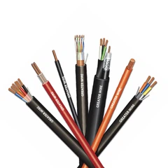
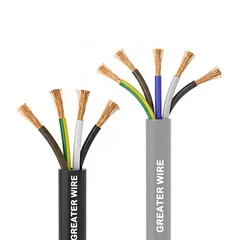
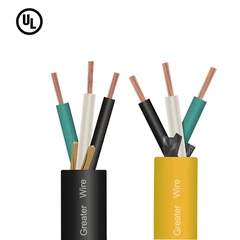
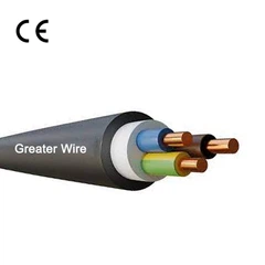

In industrial electrical systems, reliable signal transmission is just as important as dependable power distribution. Motors, variable frequency drives (VFDs), transformers, and other electrical equipment can generate electromagnetic interference (EMI), potentially affecting sensitive control and instrumentation signals.
This is why many shielded TC-ER cables incorporate a small but important component: the drain wire.
Although it is much smaller than the main conductors, the drain wire plays an essential role in shield termination and grounding. It provides a convenient electrical connection to the metallic shielding layer, making it easier to manage interference and maintain electrical continuity.
But what exactly does a drain wire do? How does it work with the cable shield, and why should engineers pay attention to it when selecting industrial cables?
This guide explains its function, construction, grounding considerations, and practical applications in industrial installations.
1. What Is a Drain Wire in Shielded TC-ER Cable?
A drain wire is a small conductive wire positioned in direct contact with the metallic shielding layer of a cable. It is commonly used in foil-shielded cables, where the shield consists of aluminum foil or an aluminum-polyester laminate.
Unlike the insulated conductors that carry power or control signals, the drain wire provides an accessible electrical connection to the shield.
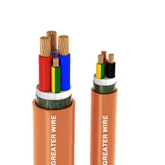
A typical shielded TC-ER control cable may contain five main components:
Conductors: Carry electrical power or control signals.
Insulation: Separates individual conductors and prevents electrical contact.
Shielding: Helps reduce electromagnetic interference.
Drain wire: Provides a convenient electrical path for terminating the shield.
Outer jacket: Protects the cable assembly against environmental and mechanical exposure.
In many foil-shielded constructions, the drain wire is made of tinned copper. It runs longitudinally alongside the foil, maintaining electrical contact with its conductive surface.
For example, Southwire specifies a shielded Type TC-ER control cable with 100% coverage aluminum foil shielding and a tinned copper drain wire. This illustrates how the two components work together in a commercial cable construction.
The important distinction is that the drain wire is not the shield itself. It is the electrical connection that makes the shield easier to terminate.


2. What Does a Drain Wire Actually Do?
The primary function of a drain wire is to provide a reliable and convenient electrical connection to the cable shield.
Its practical value can be understood through three functions.
2.1 Provides an Electrical Connection to the Shield
Thin aluminum foil is effective for providing broad shielding coverage, but it can be difficult to handle during cable termination.
Connecting directly to the foil may result in unreliable contact, particularly when the foil is damaged, folded, or improperly secured.
A drain wire solves this problem by providing a continuous conductive contact along the shield.
During installation, an electrician can expose the drain wire and connect it to the appropriate grounding or shield-termination point.
This makes shield termination more convenient and repeatable.
2.2 Helps Manage Electromagnetic Interference (EMI)
Industrial environments contain many potential sources of electromagnetic interference, including:
Variable frequency drives (VFDs).
Electric motors and motor starters.
Transformers and switching equipment.
High-current power distribution circuits.
Industrial automation machinery.
These sources can generate electromagnetic fields that couple into nearby control and instrumentation cables.
A properly designed and terminated metallic shield helps reduce unwanted interference reaching the internal conductors.
The drain wire provides the electrical connection needed to terminate that shield.
Depending on the installation and grounding arrangement, the shield can help manage unwanted coupled currents and reduce interference affecting sensitive signals.
However, the drain wire does not independently eliminate EMI. Shield coverage, cable routing, separation distances, termination quality, and the overall grounding system all influence performance.
2.3 Simplifies Shield Grounding and Termination
A cable shield must be connected according to the electrical and EMC requirements of the installation.
The drain wire provides a convenient connection point, especially when the cable uses foil shielding.
Without a drain wire, installers may need additional termination methods to establish reliable electrical contact with the foil.
With a drain wire, the connection process is generally simpler.
This is particularly useful in industrial control panels, junction boxes, and equipment connections where multiple shielded cables must be terminated.
3. How Does a Drain Wire Work with the Cable Shield?
To understand the drain wire's function, it is important to distinguish between the shield and the drain wire.
They work together, but they perform different tasks.
| Component | Main Function |
|---|---|
| Metallic shield | Reduces electromagnetic interference coupling into or out of the cable |
| Drain wire | Provides a convenient electrical connection to the foil shield |
| Signal conductor | Carries control, instrumentation, or communication signals |
| Equipment grounding conductor | Provides a fault-current path for electrical safety |
How the Drain Wire and Shield Work Together
The process can be explained in four steps:
Step 1: The shield surrounds the internal conductors.
The aluminum foil or other metallic shielding material creates a conductive layer around the conductors.
Step 2: External interference couples with the shield.
Electromagnetic fields can induce unwanted electrical currents or voltages in the shielding system.
Step 3: The drain wire provides an accessible conductive connection.
Because it remains in contact with the foil, the drain wire makes it easier to connect the shield to the designated termination point.
Step 4: The grounding and bonding arrangement manages the interference currents.
The shield termination and bonding system provide the intended electrical path, helping prevent unwanted interference from affecting signal transmission.
The actual performance depends on the entire shielding and grounding arrangement, not simply on whether a drain wire is present.

4. Drain Wire vs. Equipment Grounding Conductor: What Is the Difference?
This is one of the most important distinctions when selecting shielded industrial cables.
A drain wire and an equipment grounding conductor may both be connected to ground, but they are not interchangeable.
| Comparison | Drain Wire | Equipment Grounding Conductor |
|---|---|---|
| Primary purpose | Shield termination and EMC management | Electrical fault protection |
| Typical position | In contact with the metallic shield | Inside the cable assembly as a separate conductor |
| Typical construction | Often small-gauge tinned copper | Sized according to applicable electrical requirements |
| Carries normal load current | No | No |
| Designed for fault-current duty | Not as a substitute for an EGC | Yes, as part of the protective grounding system |
| Main application | Shielded control and instrumentation cables | Power and control circuit safety grounding |
Why Does This Difference Matter?
Consider a shielded TC-ER cable used to connect an industrial control panel to a machine.
The drain wire helps establish the electrical connection to the foil shield, supporting the cable's interference-control function.
However, if an insulation failure causes an energized conductor to contact exposed conductive equipment, the protective grounding system must provide an appropriate fault-current path.
The drain wire must not be treated as a replacement for the equipment grounding conductor.
For North American installations, cable construction and installation must comply with the applicable requirements of the NEC and the relevant product listing.
UL 1277 covers electrical power and control tray cables and recognizes constructions with or without separate grounding conductors. The presence of a shield or drain wire does not automatically satisfy the equipment grounding requirements of an installation.
For engineers and procurement teams, confirming the required grounding conductor configuration is therefore essential.
5. Should a Drain Wire Be Grounded at One End or Both Ends?
This is a common question when installing shielded TC-ER cables.
There is no universal grounding rule that applies to every shielded cable installation.
The appropriate termination method depends on the signal frequency, equipment design, EMC requirements, and potential differences between grounding points.
5.1 Single-Point Grounding
In some low-level analog instrumentation applications, grounding the shield at one end is used to reduce the risk of circulating currents caused by differences in ground potential.
This approach is often considered for:
Low-level analog signals.
Certain 4–20 mA instrumentation circuits.
Sensitive measurement systems.
Installations where ground potential differences are a concern.
However, single-point grounding is not automatically the best solution for every application.
5.2 Both-End Grounding
In many high-frequency and industrial communication applications, grounding the shield at both ends can provide a more effective path for high-frequency interference currents.
This approach is often used where the equipment manufacturer specifies low-impedance shield bonding at both ends.
However, potential differences between grounding points can produce unwanted circulating currents through the shield.
Proper equipotential bonding and grounding-system design are therefore important.
5.3 Follow the Equipment Manufacturer's EMC Instructions
For industrial automation projects, the correct shield termination method should be determined by the equipment manufacturer's installation instructions and the system's EMC design.
For example, different requirements may apply to:
PLC analog input circuits.
Industrial Ethernet connections.
VFD motor cables.
Encoder feedback cables.
High-speed communication systems.
A single-point grounding recommendation should not be applied indiscriminately to all shielded cables.
The key is to establish an intentional, low-impedance shield termination that meets the requirements of the connected equipment.

6. Where Are Drain-Wire Shielded TC-ER Cables Used?
Drain-wire shielded cables are particularly useful in industrial environments where reliable control signals and effective interference management are important.
6.1 Industrial Automation Systems
Modern automation facilities contain motors, sensors, controllers, and switching equipment operating in close proximity.
A shielded cable can help protect sensitive control signals from electromagnetic interference generated by nearby electrical equipment.
A suitable TC-ER Cable for Industrial Automation may be used for connections between control panels, machinery, and field devices, provided its electrical ratings and listing match the application.
6.2 PLC Control Systems
Programmable Logic Controllers (PLCs) receive signals from sensors and transmit commands to industrial equipment.
Interference affecting these signals can contribute to incorrect measurements, communication errors, or unreliable control operations.
A shielded PLC Control Cable with a drain wire can simplify shield termination and help maintain signal integrity when properly installed.
Typical applications include:
Analog sensor connections.
Temperature and pressure monitoring.
Industrial process control.
Machine automation.
Control panel interconnections.
6.3 Industrial Power and Control Cable Tray Installations
Cable trays frequently contain multiple cables carrying different types of electrical signals.
Power conductors, motor circuits, and control cables may be routed through the same industrial facility.
A suitable Power Tray Cable provides an installation solution for electrical power distribution, while shielded control cable constructions help address interference concerns in nearby signal circuits.
These cables should be selected according to their specific voltage ratings, conductor types, shielding requirements, and applicable installation rules.
6.4 Medium Power and Equipment Connections
In industrial facilities, electrical systems may combine power distribution, motor control, and instrumentation circuits.
Medium Power Cable Systems may be installed alongside shielded control circuits, creating a need for appropriate cable separation and EMC planning.
Drain-wire shielded control cables can help simplify shield termination in these environments, but they do not eliminate the need for proper cable routing and grounding practices.
7. Does XHHW Cable Need a Drain Wire?
Not necessarily.
XHHW and XHHW-2 describe conductor insulation types, not shielding configurations.
XHHW-2 insulated conductors are commonly used in industrial power and control cable constructions because of their electrical and thermal characteristics.
However, the presence of XHHW-2 insulation does not mean a cable automatically includes a metallic shield or drain wire.
These are separate design features.
For example, a cable may have:
XHHW-2 insulated conductors without shielding.
XHHW-2 insulated conductors with an overall foil shield.
XHHW-2 insulated conductors with foil shielding and a drain wire.
The correct construction depends on the electrical application.
What About XHHW Tray Cable?
When evaluating XHHW Tray Cable, buyers should understand that XHHW-2 identifies the insulation type of the individual conductors, while TC-ER identifies a cable type and its permitted installation applications under the applicable North American requirements.
These terms describe different aspects of cable construction and approval.
A product should not be assumed to have TC-ER approval simply because its conductors use XHHW-2 insulation.
Likewise, a drain wire is not automatically included in every XHHW-based cable.
Before purchasing, confirm the complete cable specification, including:
Conductor material and size.
Insulation type and temperature rating.
Number of conductors.
Overall shielding construction.
Drain wire material and size.
Equipment grounding conductor requirements.
Outer jacket material.
Voltage rating and applicable certifications.


8. How to Choose the Right Shielded TC-ER Cable with a Drain Wire
Selecting the right cable involves more than checking whether a drain wire is included.
Engineers and purchasing teams should evaluate the entire cable construction against the intended installation.
| Selection Factor | What to Check | Why It Matters |
|---|---|---|
| Conductor material | Bare copper or tinned copper | Determines electrical and application characteristics |
| Insulation | THHN/THWN-2, XHHW-2, or other specified type | Affects temperature, moisture, and electrical performance |
| Shielding | Aluminum foil, braid, or combined shielding | Determines shielding construction and coverage |
| Drain wire | Material, size, and contact with foil | Supports reliable shield termination |
| Grounding conductor | Separate EGC where required | Supports electrical fault protection |
| Outer jacket | PVC, CPE, or other specified material | Provides environmental and mechanical protection |
| Cable rating | UL Type TC or TC-ER as applicable | Determines permitted installation applications |
| Temperature and voltage | Product markings and listing | Ensures suitability for the intended electrical system |
Important Standards and Compliance Considerations
For North American projects, UL 1277 is an important product standard for electrical power and control tray cables.
It covers cable constructions with optional metal shields and separate grounding conductors.
NEC Article 336 addresses Type TC cable installation, including applicable requirements for exposed-run applications.
UL 44 is relevant when XHHW or XHHW-2 insulated conductors are specified.
However, these standards address different aspects of cable design and installation. Compliance with one standard does not automatically establish compliance with every other requirement.
Buyers should verify the actual product markings, listing, construction, and intended installation conditions rather than relying on a generic cable description.
For projects outside North America, IEC, CSA, and AS/NZS requirements should be evaluated separately. UL Type TC-ER terminology should not be assumed to establish compliance with another country's cable classification or installation rules.
9. Common Mistakes When Using Drain-Wire Shielded Cables
Even when a suitable shielded cable is selected, incorrect installation can reduce its effectiveness.
Here are five common mistakes to avoid.
Mistake 1: Treating the drain wire as an equipment grounding conductor.
The drain wire is intended for shield termination. It must not replace a required protective grounding conductor.
Mistake 2: Assuming every shield should be grounded at one end.
Grounding requirements depend on the signal type, interference frequency, equipment instructions, and bonding arrangement.
Mistake 3: Leaving the drain wire disconnected.
An unconnected drain wire may leave the foil shield without its intended electrical termination.
Mistake 4: Damaging the foil during cable preparation.
Excessive stripping or improper handling can damage the shielding layer and compromise its continuity.
Mistake 5: Assuming shielding eliminates all interference.
Even a properly shielded cable can experience interference problems if it is routed incorrectly or terminated poorly.
Maintaining appropriate separation from noisy power circuits, using suitable termination hardware, and following equipment-specific EMC instructions are all important.
10. Frequently Asked Questions About Drain Wires
Q1: Does every shielded TC-ER cable have a drain wire?
No. Shielded TC-ER cables may use different shielding constructions, including foil, braid, or combined shielding.
Foil-shielded designs commonly incorporate a drain wire to simplify electrical termination, but not every shielded cable requires one.
Always check the manufacturer's construction specification.
Q2: Is a drain wire always made of copper?
No, although copper and tinned copper are common materials.
Tinned copper is frequently used because the tin coating helps improve resistance to oxidation and supports reliable electrical connections.
The actual material and conductor size should be confirmed from the product specification.
Q3: Does a drain wire carry the normal operating current?
No. Its primary purpose is to provide an electrical connection to the metallic shield.
It is not intended to function as a normal load-current conductor or as a substitute for a protective grounding conductor.
Q4: Can I use shielded TC-ER cable without connecting the drain wire?
A shielded cable with an unterminated drain wire may not provide the intended shield connection.
The correct termination method depends on the application and the cable design. Follow the manufacturer's instructions and the equipment's EMC requirements.
Q5: Is a drain wire necessary for PLC applications?
Not every PLC cable requires a drain wire.
However, shielded cable constructions are often useful for sensitive analog signals and other circuits exposed to electromagnetic interference.
A drain wire makes it easier to terminate the foil shield when that construction is used.
Q6: Does a drain wire improve cable safety?
Its primary function is related to shielding and EMC, not electrical shock protection.
Electrical safety depends on the correct conductor insulation, protective grounding system, overcurrent protection, and compliant installation.
A drain wire should never be considered a replacement for an equipment grounding conductor.
Conclusion
A drain wire may be one of the smallest components in a shielded TC-ER cable, but it serves an important purpose. By providing a convenient electrical connection to the metallic shield, it simplifies shield termination and supports effective electromagnetic interference management.
For industrial engineers, electrical contractors, and cable procurement professionals, understanding the difference between the shield, drain wire, and equipment grounding conductor is essential when specifying the right cable.
The best cable selection is not simply the one with the most shielding or additional components. It is the one whose complete construction, electrical ratings, grounding arrangement, and certifications match the actual installation requirements.
Looking for Reliable Shielded TC-ER Cable Solutions?
At GERITEL WIRE, we understand that industrial cable selection involves more than choosing conductor size and insulation material. Shielding construction, drain wire configuration, grounding requirements, and applicable certifications all contribute to a reliable cable solution. Whether your project requires shielded TC-ER control cables, XHHW-2 insulated constructions, or customized cable solutions for industrial automation and power distribution, our team is ready to discuss your technical and procurement requirements. Contact GERITEL WIRE to explore suitable cable specifications, discuss customization options, and request a quotation for your next project.
Dongguan Greater Wire & Cable Co., Ltd.
Tel/WhatsApp/Wechat: +86 136 6257 9592
Tel/WhatsApp/Wechat: +86 135 1078 4550
Email: manager01@greaterwire.com
Website: www.greaterwire.com