



Corrosion around electrical cable connections is more than a cosmetic problem. It can increase electrical resistance, weaken mechanical connections, interrupt bonding continuity, and eventually contribute to overheating or equipment failure. For electrical contractors, engineers, facility managers, and cable buyers, understanding why corrosion develops around cable terminations is essential for maintaining reliable power distribution systems.
Although ACWU90 is designed for demanding electrical installations, its protective construction does not make every connection corrosion-proof. Moisture, incompatible metals, improper termination practices, damaged protective coatings, and unsuitable cable glands can all contribute to corrosion around connection points.
This guide explains the most common causes of corrosion around ACWU90 cable connections, how to recognize early warning signs, and what installation and maintenance practices can help prevent connection deterioration.
1. Understanding Where Corrosion Can Occur Around ACWU90 Connections
Before identifying the causes, it is important to understand the different components involved in an ACWU90 cable termination.
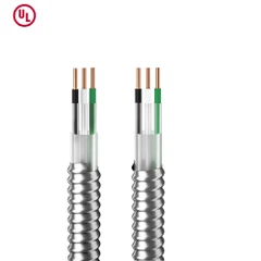
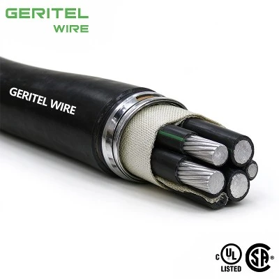
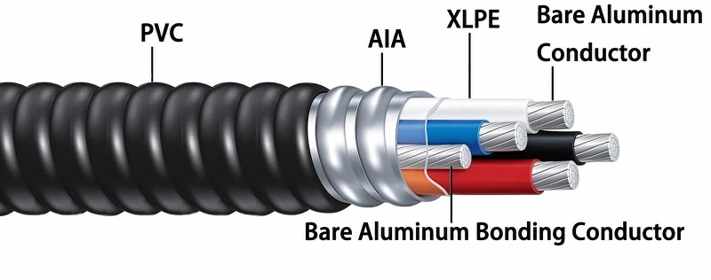
A typical ACWU90 construction may include:
Conductor: Aluminum or copper, depending on the specific product.
Insulation: Cross-linked polyethylene (XLPE), commonly rated RW90.
Bonding conductor: A separate conductor provided according to the cable design.
Armour: Aluminum interlocked armour (AIA).
Outer jacket: Commonly a protective PVC covering.
The exact construction must always be confirmed from the manufacturer's datasheet and cable markings. Not every product sold under the ACWU90 designation has identical materials or conductor arrangements.
At the termination point, several components may come into contact:
The exposed conductor and electrical lug.
The lug and equipment terminal or busbar.
The metallic armour and cable gland.
The cable gland and electrical enclosure.
The bonding conductor and bonding terminal.
The enclosure, mounting hardware, and environmental sealing components.
Corrosion can develop at any of these interfaces.
| Location | Potential corrosion problem | Possible consequence |
|---|---|---|
| Aluminum conductor and lug | Aluminum oxidation or galvanic corrosion | Increased contact resistance |
| Copper-to-aluminum connection | Galvanic corrosion in the presence of moisture | Deterioration of the contact interface |
| Cable gland and armour | Material incompatibility or moisture exposure | Corrosion of metallic components |
| Gland and enclosure interface | Damaged coating or water ingress | Surface corrosion and loss of protection |
| Bonding connection | Corrosion or loose hardware | Reduced bonding reliability |
| Internal terminal compartment | Condensation or water entry | Corrosion of multiple electrical components |
Identifying the exact location is the first step toward determining the correct corrective action.
2. Common Causes of Corrosion Around ACWU90 Cable Connections
2.1 Moisture and Water Ingress
Moisture is one of the most important factors contributing to corrosion around electrical connections.
Even when a cable has a moisture-resistant outer jacket, water can still enter through an improperly installed cable gland, damaged enclosure seal, loose cover, or unsuitable termination accessory.
Once moisture reaches an exposed metal connection, it can create conditions that accelerate corrosion.
Common sources of moisture include:
Rainwater entering outdoor electrical enclosures.
Condensation caused by temperature changes.
Water entering underground junction boxes.
High humidity in industrial environments.
Water exposure during equipment cleaning.
Damaged or incorrectly installed enclosure gaskets.
Moisture is particularly problematic when different metals are in electrical contact. Water containing dissolved salts or other contaminants can act as an electrolyte, allowing electrochemical corrosion to occur.
For example, an aluminum conductor connected to a copper busbar may experience galvanic corrosion if the connection is not properly designed and protected and moisture reaches the interface.
Important: A cable rated for use in wet locations does not automatically make every connected enclosure, gland, or terminal suitable for wet-location service. The complete termination assembly must be suitable for its actual environment.
2.2 Galvanic Corrosion Between Dissimilar Metals
Galvanic corrosion occurs when two different metals are electrically connected in the presence of an electrolyte, such as water containing dissolved salts.
One metal becomes more susceptible to corrosion while the other supports the electrochemical reaction.
This is particularly relevant to electrical connections involving aluminum and copper.
For example, consider an aluminum conductor connected directly to an incompatible copper terminal in a damp environment. If moisture reaches the interface, galvanic corrosion may gradually deteriorate the connection.
Potentially problematic combinations include:
Aluminum conductors and incompatible copper terminals.
Aluminum armour and unsuitable metallic gland components.
Aluminum enclosures and incompatible mounting hardware.
Dissimilar metals with damaged or inadequate protective coatings.
However, the presence of two different metals does not automatically mean a connection will fail.
Electrical connectors are available in materials and configurations specifically evaluated for aluminum-to-copper connections. Tin-plated connectors, properly rated dual-metal connectors, and other approved transition arrangements can help control the risk.
The important considerations are connector suitability, material compatibility, environmental exposure, and correct installation.
For ACWU90 installations, contractors should not select cable glands or terminal accessories based only on physical fit. Their material compatibility with the cable armour, enclosure, and conductor must also be considered.
2.3 Aluminum Oxidation at Conductor Terminations
Aluminum naturally reacts with oxygen in the surrounding air, forming a thin aluminum oxide layer on its surface.
This is a normal chemical characteristic of aluminum, but it is important in electrical connections.
Unlike the oxide formed on copper, aluminum oxide has relatively high electrical resistance. If the conductor-to-terminal interface is improperly prepared or assembled, oxide and other contaminants can contribute to poor electrical contact.
A poor connection can create additional problems:
Contact resistance increases.
Electrical current generates more heat at the connection.
Thermal cycling places additional stress on the connection.
The connection may loosen or deteriorate further.
Local overheating can eventually damage the terminal or surrounding insulation.
It is important to distinguish ordinary surface oxidation from active corrosion.
A thin, naturally formed oxide film is not necessarily evidence of a defective connection. The greater concern is an improperly prepared or contaminated contact surface, moisture exposure, incompatible materials, or deterioration that affects the electrical and mechanical integrity of the connection.
For aluminum conductors, appropriate preparation and connector selection are essential.
Under the 2024 Canadian Electrical Code (CEC), Rule 12-118 addresses precautions for terminating and splicing aluminum conductors. These include appropriate conductor preparation, cleaning of stranded conductors, compatible fittings, and the use of suitable joint compound unless the termination or splice is marked for use without it.
The specific connector manufacturer's instructions must also be followed.
2.4 Incorrect Connector or Cable Gland Selection
A cable gland or electrical connector may physically fit a cable without being suitable for its construction or installation environment.
This is a common source of problems during installation and equipment maintenance.
For example, an unsuitable cable gland may:
Fail to seal properly around the outer jacket.
Provide inadequate mechanical retention.
Be incompatible with the cable's aluminium interlocked armour.
Create an unsuitable metal-to-metal interface.
Fail to maintain the required enclosure ingress protection.
Allow water or contaminants to reach internal connections.
The material of the gland also matters.
Depending on the application, cable glands may be manufactured from brass, nickel-plated brass, aluminum, stainless steel, or other materials. Their suitability depends on the cable armour, enclosure material, environmental conditions, and applicable certification requirements.
For example, a gland selected for an ordinary indoor installation may not provide sufficient corrosion resistance for a coastal or chemical-processing environment.
When selecting a gland, check:
Cable construction and armour material.
Overall cable outside diameter.
Cable gland clamping range.
Enclosure entry thread and material.
Required ingress protection rating.
Environmental corrosion exposure.
Electrical bonding and grounding requirements.
Applicable hazardous-area certification, if required.
A properly selected gland helps maintain the environmental seal and mechanical integrity of the termination.
2.5 Improper Termination and Installation Practices
Even a high-quality connector can deteriorate if it is installed incorrectly.
Common installation mistakes include:
Using a connector that is not rated for the conductor material.
Failing to follow the connector manufacturer's conductor preparation instructions.
Applying an unsuitable oxide-inhibiting compound.
Using the wrong crimping tool or die.
Tightening mechanical terminals below or above the specified torque.
Damaging the connector's protective plating.
Leaving exposed conductor strands outside the intended contact area.
Failing to maintain the required environmental seal.
Incorrect tightening is particularly important.
A connection that is too loose may have insufficient contact pressure, resulting in increased resistance and localized heating. Excessive tightening can damage the conductor, connector, or terminal hardware.
Neither condition should be treated as a corrosion problem alone. The electrical and mechanical condition of the connection must be assessed together.
Installers should follow the connector manufacturer's specified preparation, tooling, and torque requirements rather than relying on general assumptions.
2.6 Salt, Chemicals, and Industrial Contaminants
Electrical installations in coastal, marine, wastewater treatment, chemical processing, and heavy industrial environments may experience more aggressive corrosion conditions.
Common environmental contaminants include:
Salt spray and airborne chlorides.
Industrial chemical vapours.
Cleaning chemicals.
Sulphur-containing compounds.
Chemical residues and contaminated water.
Dust combined with moisture.
Saltwater is particularly aggressive because dissolved salts increase the electrical conductivity of water and can accelerate electrochemical corrosion.
Industrial contaminants may also damage protective coatings or attack exposed metal surfaces.
For example, a cable termination installed near a coastal processing facility may experience repeated salt deposition and condensation. If the enclosure seal is damaged, moisture and salt can reach the metallic connection components.
In these environments, standard indoor electrical accessories may not provide adequate long-term corrosion resistance.
The complete connection assembly should be evaluated for the actual exposure conditions, including the cable gland, enclosure, fasteners, terminal hardware, and sealing accessories.
2.7 Damaged Protective Coatings and Cable Jacket
Protective coatings and cable jackets help reduce exposure of metallic components to moisture and contaminants.
However, their effectiveness depends on their condition and correct installation.
Corrosion risks may increase when:
A cable jacket is cut or damaged near the termination.
Gland installation damages the jacket sealing surface.
Protective plating on a connector is scratched or removed.
A metallic enclosure has damaged paint or coating.
Improper tools damage the gland or terminal assembly.
Unused enclosure openings are left without suitable plugs.
ACWU90 commonly uses a PVC outer jacket over aluminum interlocked armour. The jacket helps protect the underlying metallic construction, but it does not eliminate the need for suitable termination accessories and proper environmental sealing.
If the jacket is damaged near a connection, water may reach the armour or other internal components. The extent of the damage must be assessed before the installation is returned to service.

3. How to Recognize Corrosion Around ACWU90 Connections
Early identification can help prevent a minor connection problem from developing into a more serious electrical failure.
However, visible corrosion is not the only warning sign. Some deteriorating connections develop overheating or electrical performance problems before substantial external corrosion becomes visible.
3.1 Visible Warning Signs
During an appropriate inspection, possible warning signs include:
White or grey deposits around exposed aluminum surfaces.
Green or blue-green deposits around copper components.
Rust on steel fasteners or enclosure hardware.
Discoloration around terminal connections.
Damaged or peeling connector plating.
Water stains or moisture deposits inside enclosures.
Cracked or deteriorated cable gland seals.
Corrosion products around armour termination points.
The appearance of corrosion products can provide clues about the affected material, but appearance alone cannot reliably identify the corrosion mechanism.
For example, white deposits may be associated with aluminum corrosion products, while green deposits may indicate copper corrosion. Further inspection is necessary to establish the actual cause.
3.2 Electrical and Mechanical Warning Signs
Other symptoms may indicate that a connection has deteriorated:
| Warning sign | Possible underlying issue |
|---|---|
| Localized overheating | High contact resistance or loose connection |
| Intermittent power supply | Unstable electrical contact |
| Repeated terminal failures | Incorrect connector selection or installation |
| Unusual electrical odour | Overheating or insulation deterioration |
| Damaged terminal insulation | Excessive heat or mechanical damage |
| Reduced bonding continuity | Corroded or loose bonding connection |
Thermal imaging can help identify abnormal temperature patterns during an appropriately planned inspection. However, temperature measurements alone cannot establish whether corrosion is the cause.
Electrical testing and physical inspection should be performed by qualified personnel using procedures appropriate to the equipment and installation.
4. How to Prevent Corrosion Around ACWU90 Cable Connections
Preventing corrosion requires more than choosing a corrosion-resistant cable. The conductor, connector, gland, enclosure, and installation environment must be considered as one complete system.
4.1 Use Connectors Rated for the Conductor Material
The connector must be specifically suitable for the conductor material and size.
For aluminum conductors, verify that the terminal or connector is identified for aluminum conductor use. Where a copper-to-aluminum transition is required, use an appropriately rated connector designed for that combination.
Check the connector markings and manufacturer's technical documentation before installation.
Relevant considerations include:
Conductor material: copper, aluminum, or both.
Conductor size and stranding class.
Voltage and temperature ratings.
Connector application and environmental suitability.
Required installation tooling.
Applicable product certification.
For projects in Canada, CEC Rule 12-118 requires equipment connected to aluminum conductors to be appropriately marked for that purpose, subject to the stated exceptions.
In the United States, connector selection and installation must follow the applicable NEC requirements and the listing and instructions for the connector. UL 486A-486B is a relevant connector product standard, but compliance with a connector standard does not replace installation-code requirements.
4.2 Prepare Aluminum Conductors Correctly
Aluminum conductors require appropriate preparation before termination.
Depending on the connector design and its instructions, preparation may include:
Removing insulation without damaging the conductor strands.
Cleaning the conductor as instructed.
Removing excessive surface contamination or oxide where specified.
Applying an approved joint compound when required.
Inserting the conductor to the correct depth.
Tightening or crimping using the specified method.
CEC Rule 12-118 specifically addresses cleaning stranded aluminum conductors and the use of joint compound capable of penetrating the oxide film and preventing its reforming, unless the termination or splice is marked for use without compound.
Do not assume that every connector requires the same brushing or compound procedure. Some connectors are supplied pre-filled, and some are specifically marked for installation without additional compound.
The connector manufacturer's instructions take priority for the particular product.
4.3 Select Compatible Cable Glands and Accessories
Cable glands should be selected according to the cable construction and environmental conditions.
For ACWU90, confirm that the gland is suitable for the cable's overall diameter and aluminum interlocked armour.
The gland must also be compatible with the enclosure and provide the required mechanical retention, sealing, and bonding arrangement.
For outdoor or corrosive environments, consider:
Corrosion-resistant gland materials.
Suitable plating or protective coatings.
Compatible enclosure entry materials.
Correct sealing washers and gaskets.
Appropriate ingress protection.
Compatible locknuts and other accessories.
In highly corrosive environments, stainless steel or specially protected gland materials may be appropriate. However, no single gland material is suitable for every installation.
Material compatibility and environmental suitability should be confirmed using the gland manufacturer's technical documentation.
4.4 Maintain Proper Enclosure Sealing
An electrical enclosure protects internal connections from environmental exposure only when its complete assembly is correctly installed.
Important measures include:
Use enclosures with an appropriate environmental rating.
Install cable glands according to their instructions.
Ensure gaskets are correctly positioned and undamaged.
Seal unused cable entries with suitable accessories.
Tighten enclosure covers and fasteners correctly.
Avoid installation arrangements that direct water toward cable entries.
Inspect seals after maintenance or equipment modification.
Where condensation is likely, the enclosure design may also require suitable drainage, ventilation, or condensation-control measures.
Any such measures must preserve the enclosure's required environmental protection and comply with the applicable installation requirements.
4.5 Protect Connections in Harsh Environments
Coastal, marine, chemical, and industrial installations require additional attention to corrosion protection.
Depending on the site conditions, suitable measures may include:
Corrosion-resistant enclosures and gland materials.
Compatible protective coatings.
Properly selected sealing systems.
Protection against salt deposits and chemical contamination.
Appropriate equipment placement.
Periodic inspection and cleaning.
Protective compounds and coatings should only be used when they are compatible with the connector, cable, enclosure, and electrical application.
Do not apply general-purpose grease, paint, or sealant to an electrical contact surface unless the relevant manufacturer specifically permits it.
4.6 Follow the Correct Installation Torque and Tooling Requirements
Correct mechanical assembly is essential for maintaining a reliable electrical connection.
For mechanical terminals, use the torque specified by the connector or equipment manufacturer. A calibrated torque tool should be used where required.
For compression connectors, use the specified crimping tool, die, and installation sequence.
Incorrect tooling can result in inadequate compression, damaged connectors, or poor electrical contact.
Installers should also ensure that:
Conductors are fully inserted.
No unintended strands are left outside the terminal.
Connector surfaces are not damaged.
Cable glands are correctly assembled.
Cable bending does not place excessive mechanical stress on the termination.
4.7 Establish a Regular Inspection and Maintenance Program
Connections in outdoor and industrial environments should be inspected according to the equipment manufacturer's recommendations, site conditions, and maintenance program.
A practical inspection checklist may include:
| Inspection item | What to check |
|---|---|
| Cable jacket | Cuts, cracks, abrasion, or other damage |
| Cable gland | Correct installation, sealing, and corrosion |
| Enclosure | Water ingress, damaged gaskets, or corrosion |
| Conductor terminal | Visible deterioration or discoloration |
| Connector hardware | Corrosion, damage, or signs of movement |
| Bonding connection | Mechanical security and electrical continuity |
| Operating temperature | Abnormal temperature rise |
| Environmental exposure | Salt, chemicals, condensation, or standing water |
Any inspection involving opening electrical enclosures or testing energized equipment must be performed by qualified personnel under appropriate electrical safety procedures.
5. What Should You Do If Corrosion Is Already Present?
If corrosion is discovered around an ACWU90 connection, simply wiping away the visible deposits is not enough.
The underlying cause must be identified, and the electrical integrity of the connection must be evaluated.
A suitable corrective process generally involves the following steps.
Step 1: Make the Equipment Safe
Electrical connections should not be disturbed while energized unless a specific procedure and authorization permit the work.
Qualified personnel should follow the applicable isolation, lockout/tagout, and verification procedures before inspecting or repairing the connection.
Step 2: Identify the Affected Components
Determine whether corrosion is present on:
The conductor.
The electrical lug.
The equipment terminal.
The cable gland.
The armour termination.
The bonding connection.
The enclosure or mounting hardware.
The location helps determine whether the problem is caused by conductor oxidation, galvanic corrosion, moisture ingress, chemical exposure, or installation defects.
Step 3: Determine the Extent of Damage
Inspect whether corrosion has affected only the external surface or has compromised the connection.
Check for:
Material loss.
Damaged plating.
Pitting or deformation.
Loose terminal hardware.
Conductor strand damage.
Reduced mechanical strength.
Evidence of overheating.
Damaged insulation or cable jacket.
A connector with significant corrosion, damaged contact surfaces, or compromised mechanical integrity may require replacement.
Step 4: Correct the Underlying Cause
Replacing a corroded connector without correcting the original problem may only result in another failure.
For example:
| Identified cause | Corrective action |
|---|---|
| Water entering through cable gland | Replace or correctly reinstall suitable sealing components |
| Incompatible conductor and connector materials | Select a connector rated for the conductor combination |
| Incorrect aluminum conductor preparation | Re-terminate according to connector instructions and applicable code |
| Damaged enclosure gasket | Replace with a compatible gasket |
| Corrosive chemical exposure | Select more suitable materials and protective measures |
| Loose or improperly installed terminal | Reassemble using the manufacturer's specified procedure |
Step 5: Test and Document the Repair
After repair, qualified personnel should verify the connection using appropriate inspection and testing procedures.
Depending on the equipment and installation, this may include:
Mechanical inspection.
Verification of conductor termination.
Bonding continuity testing.
Insulation resistance testing where appropriate.
Electrical performance checks.
Thermal inspection under suitable operating conditions.
The repair should be documented, including the identified cause, replacement components, installation method, and test results.
6. Does ACWU90 Cable Itself Cause Corrosion?
No. The ACWU90 designation does not mean that the cable inherently causes corrosion around electrical connections.
Corrosion is generally associated with the interaction between materials and their surrounding environment, together with the condition and installation of the connection.
However, the cable's construction influences which materials and accessories must be considered.
For example, an aluminum-conductor ACWU90 product may require terminals suitable for aluminum conductors. Its aluminum interlocked armour also needs compatible termination accessories.
A typical ACWU90 cable with an aluminum conductor, aluminum armour, and PVC outer jacket has different material interfaces from a cable using copper conductors or a different armour construction.
Therefore, buyers and contractors should verify the actual product construction instead of relying only on the ACWU90 name.
The following distinction is important:
| Cable or component feature | What it helps address | What it does not guarantee |
|---|---|---|
| XLPE insulation | Electrical insulation and thermal performance | Corrosion-free terminal connections |
| Aluminum interlocked armour | Mechanical protection | Complete protection against moisture at terminations |
| PVC outer jacket | Protection against specified environmental exposure | Waterproof performance of every cable gland |
| Aluminum bonding conductor | A bonding path in the specified cable construction | Permanent corrosion resistance at every bonding connection |
| Corrosion-resistant connector | Improved suitability for specified environments | Correct installation or compatibility with every metal |
The complete cable termination system must be selected and installed correctly.
7. Important Standards and Requirements for Corrosion Prevention
Different standards address different parts of an electrical installation. A cable product standard, connector product standard, and electrical installation code should not be treated as interchangeable.
7.1 Canadian Electrical Code (CEC)
For Canadian ACWU90 installations, the applicable edition of CSA C22.1, Canadian Electrical Code, Part I, should be checked along with provincial or territorial adoption and amendments.
The 2024 CEC includes several relevant requirements:
| CEC reference | General subject | Relevance to corrosion prevention |
|---|---|---|
| Rule 12-116 | Termination of conductors | Addresses acceptable conductor termination methods |
| Rule 12-118 | Termination and splicing of aluminum conductors | Addresses aluminum conductor preparation, joint compound, compatible fittings, and protection in wet locations |
| Rule 12-608 | Continuity of armoured cable | Relevant to armour continuity and connection to equipment |
| Rule 12-610 | Terminating armoured cable | Addresses protection where conductors emerge from armour |
Rule 12-118 is particularly important.
It requires precautions when terminating or splicing aluminum conductors, including suitable conductor preparation and compatible fittings. It also addresses joint compound and the protection of aluminum terminations in wet locations.
This does not mean every connection must use the same compound or connector. The applicable Code wording, connector markings, and manufacturer's instructions must be considered together.
7.2 UL Standards for the North American Market
For projects in the United States, connector selection should follow the applicable National Electrical Code (NEC), product listing, and manufacturer's instructions.
UL 486A-486B addresses wire connectors for use with copper and/or aluminum conductors, within its scope.
The connector's markings are important because they identify the conductor materials and applications for which it has been evaluated.
A UL-compliant connector does not automatically make an entire ACWU90 cable assembly UL-listed. Cable certification and connector certification are separate matters.
7.3 IEC and AS/NZS Markets
For projects outside North America, applicable IEC or AS/NZS requirements must be identified according to the local electrical regulations and installation environment.
Relevant considerations may include:
Cable and conductor suitability.
Electrical connection requirements.
Cable gland and enclosure protection.
Earthing and bonding.
Corrosion protection in the installation environment.
Hazardous-area requirements, where applicable.
IEC 60079-14 is relevant to electrical installations in explosive atmospheres where its scope applies. It should not be treated as a general cable corrosion standard.
Similarly, compliance with an IEC or AS/NZS cable standard does not automatically establish that a Canadian ACWU90 product is approved for use in another market.
Always verify the exact cable, connector, gland, and installation approvals required by the local authority having jurisdiction.
8. Common Mistakes to Avoid When Preventing Connection Corrosion
Even experienced installation teams can overlook details that contribute to connection deterioration.
The following mistakes are particularly important to avoid.
| Common mistake | Why it is a problem | Better practice |
|---|---|---|
| Assuming the cable jacket makes the connection waterproof | Terminations and enclosures have separate sealing requirements | Verify the complete termination assembly |
| Connecting aluminum conductors to unsuitable copper terminals | May create an incompatible metal interface | Use connectors specifically rated for the conductor combination |
| Ignoring aluminum conductor preparation | Can compromise the contact interface | Follow CEC requirements and connector instructions |
| Applying any available anti-oxidant compound | Some compounds are not approved for the connector or application | Use only specified compatible compounds |
| Selecting a gland based only on cable diameter | Armour, sealing, and bonding requirements may be overlooked | Verify the complete cable construction and gland specification |
| Using ordinary indoor accessories outdoors | Environmental protection may be insufficient | Select accessories for actual exposure conditions |
| Tightening terminals by feel | Incorrect contact pressure may result | Follow specified torque and tooling requirements |
| Cleaning corrosion without investigating its cause | The original failure mechanism remains | Identify and correct the source of deterioration |
Avoiding these mistakes helps reduce premature connection failures, maintenance costs, and unexpected equipment downtime.
9. Practical Checklist for ACWU90 Cable Buyers and Contractors
When purchasing ACWU90 and planning its termination, consider the following checklist.
Cable specifications
Confirm whether the conductor is aluminum or copper.
Verify the conductor size and number of cores.
Confirm the insulation and armour construction.
Check the outer jacket material and applicable environmental ratings.
Verify the cable's certification and intended application.
Connector and gland selection
Confirm conductor-to-connector compatibility.
Verify connector voltage and temperature ratings.
Check the cable gland's compatibility with aluminum interlocked armour.
Confirm the required cable diameter range.
Verify enclosure material compatibility.
Check sealing and ingress protection requirements.
Confirm bonding and grounding arrangements.
Installation and maintenance
Follow the applicable electrical code.
Prepare conductors according to connector instructions.
Use approved joint compound where required.
Apply the specified torque or crimping method.
Protect exposed connections from moisture and contaminants.
Inspect cable glands, enclosures, and bonding connections periodically.
Investigate corrosion rather than simply removing visible deposits.
Completing these checks before installation can help contractors and project purchasers reduce the risk of corrosion-related connection problems.

10. Frequently Asked Questions
Does ACWU90 cable resist corrosion?
ACWU90 construction commonly includes aluminum interlocked armour and a protective PVC outer jacket. These components provide specified mechanical and environmental protection, but they do not make every termination corrosion-proof. The connector, cable gland, enclosure, and exposed metal interfaces must also be suitable for the installation environment.
Can aluminum oxidation cause ACWU90 connection failure?
Yes, improper aluminum conductor termination can contribute to increased contact resistance and overheating. Aluminum naturally forms an oxide layer, so suitable conductor preparation and connector selection are important. Follow the applicable electrical code and the connector manufacturer's instructions.
Is anti-oxidant compound always required for aluminum ACWU90 connections?
Not necessarily. Under the 2024 Canadian Electrical Code Rule 12-118, joint compound is required for terminating or splicing stranded aluminum conductors unless the termination or splice is marked for use without compound. Always follow the specific connector instructions and applicable local requirements.
Can copper and aluminum be connected in the same ACWU90 installation?
Yes, where the connection is made using a connector specifically rated for the conductor combination and the installation meets applicable requirements. Direct contact between incompatible copper and aluminum components in the presence of moisture can create galvanic corrosion risks.
Does a PVC outer jacket prevent water from entering cable connections?
No. The PVC jacket protects the cable construction within its specified performance limits, but water can still enter through improperly installed glands, damaged seals, or enclosure openings. The complete termination assembly must provide the required environmental protection.
What is the best cable gland material for ACWU90?
There is no single best material for every application. Brass, nickel-plated brass, aluminum, and stainless steel glands may be suitable depending on the cable armour, enclosure material, environmental exposure, and applicable certification. The gland manufacturer's compatibility and installation information should be checked before selection.
Can a corroded ACWU90 cable connection simply be cleaned?
Not always. Surface deposits may be removable, but corrosion can also cause pitting, material loss, damaged plating, poor electrical contact, or weakened mechanical connections. Qualified personnel should assess the damage and determine whether cleaning, re-termination, or component replacement is appropriate.
Conclusion
Corrosion around ACWU90 cable connections is usually associated with moisture exposure, galvanic interaction between dissimilar metals, aluminum oxidation, unsuitable connectors, incorrect installation practices, or aggressive environmental conditions. Preventing these problems requires attention to the entire termination system rather than the cable alone.
For electrical contractors and project buyers, the most important steps are to verify conductor and connector compatibility, select suitable cable glands, maintain effective enclosure sealing, follow the applicable electrical code, and use manufacturer-approved termination procedures. Early inspection and proper corrective action can help maintain reliable electrical connections and reduce unnecessary maintenance costs.
When selecting ACWU90 for commercial, industrial, or infrastructure projects, GERITEL WIRE can support your evaluation of cable construction, conductor options, armour configuration, and project-specific requirements. Our team understands the importance of matching cable specifications with the intended installation environment and connection accessories. Contact GERITEL WIRE to discuss your ACWU90 cable requirements, request product information, and evaluate suitable cable solutions for your electrical distribution projects.
Dongguan Greater Wire & Cable Co., Ltd.
Tel/WhatsApp/Wechat: +86 136 6257 9592
Tel/WhatsApp/Wechat: +86 135 1078 4550
Email: manager01@greaterwire.com
Website: www.greaterwire.com