

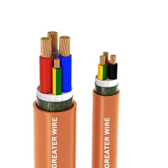
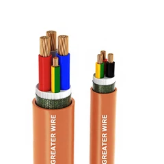

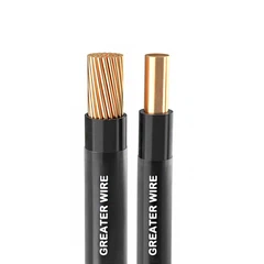
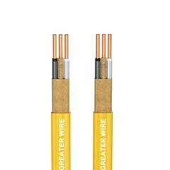
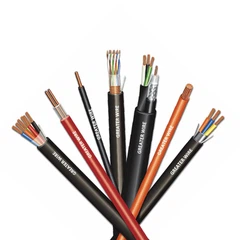
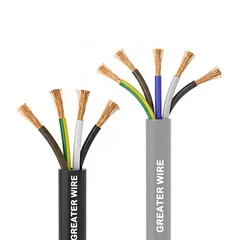
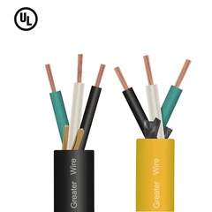
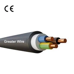

Calculating the ampacity of a buried cable circuit is more complicated than selecting a conductor size from a standard ampacity table. Underground conditions affect how quickly a cable can release the heat generated by electrical current. Soil thermal resistivity, burial depth, cable spacing, conductor material, installation arrangement, and surrounding temperature can all influence the cable's allowable current.
For ACWU90 cable, the calculation also requires attention to its XLPE insulation, aluminum interlocked armour, outer jacket, and the applicable installation rules. Although the 90°C insulation rating is an important design input, it does not automatically mean that the cable can carry the current listed in a 90°C ampacity column under every buried condition.
This guide explains the main factors, calculation workflow, and information engineers and procurement teams should verify when evaluating this cable type for underground power distribution.
1. What Is Ampacity and Why Does Underground Installation Matter?
Ampacity is the maximum current a conductor can carry continuously under specified conditions without exceeding its permitted temperature limit.
When electrical current flows through a conductor, electrical resistance generates heat. If the heat cannot escape quickly enough, the conductor temperature rises.
In an underground installation, heat must travel through the cable insulation, internal cable components, outer jacket, and surrounding soil before dissipating into the ground.
The soil therefore plays an important role in determining the allowable current.
1.1 Why Is Buried Cable Ampacity Different From Aboveground Ampacity?
A cable installed in an open-air environment can release heat differently from one buried directly in soil or installed in an underground duct.
Underground installations may experience:
Higher soil temperatures.
Poor heat dissipation in dry or high-resistivity soil.
Heat accumulation when multiple cables are installed close together.
Different thermal conditions at different burial depths.
Additional thermal resistance from ducts, concrete, or surrounding materials.
For this reason, an ampacity value published for a cable under a particular ambient-temperature condition should not automatically be used for every underground installation.
1.2 What Makes ACWU90 Different?
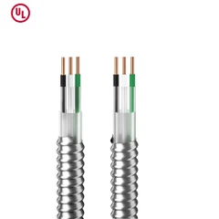
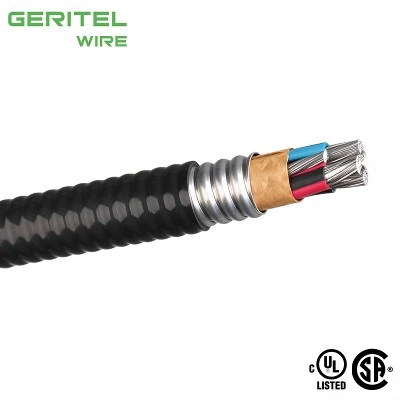
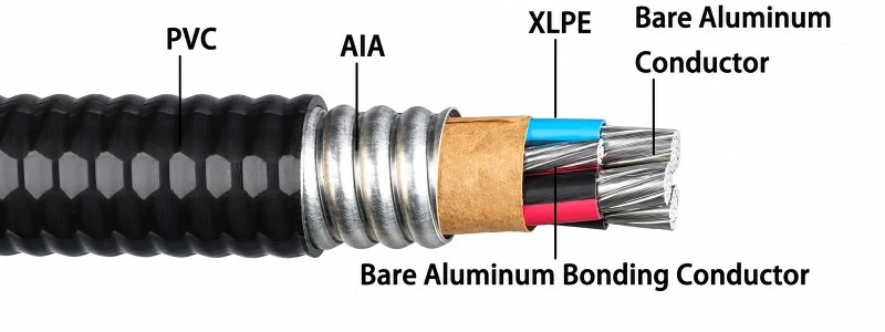
A typical ACWU90 construction includes:
| Component | Typical Material | Function |
|---|---|---|
| Conductor | Aluminum or copper, depending on the product | Carries electrical current |
| Insulation | RW90 cross-linked polyethylene (XLPE) | Provides electrical insulation |
| Bonding conductor | Depends on the certified construction | Provides an electrical bonding path |
| Armour | Interlocked aluminum armour (AIA) | Provides mechanical protection |
| Outer jacket | Commonly PVC | Protects the cable against environmental exposure |
For example, Nexans describes its ACWU90 product as a 600 V cable with RW90 XLPE insulation, interlocked aluminum armour, and a sunlight-resistant PVC outer jacket. Its product information identifies direct burial as an approved application, subject to protection requirements imposed by the inspection authority.
The actual construction and electrical ratings must always be verified against the selected manufacturer's datasheet.
2. Which Standards Apply to ACWU90 Underground Ampacity?
For projects in Canada, the main reference is the Canadian Electrical Code (CEC), CSA C22.1.
The applicable edition depends on the province or territory and its adoption and amendment arrangements.
2.1 Canadian Electrical Code Rule 4-004
CEC Rule 4-004 addresses the ampacity of wires and cables.
For underground installations, the applicable requirements distinguish between standard installation assumptions and installations requiring more precise calculations.
Alberta Municipal Affairs published STANDATA bulletin 24-ECB-004 in April 2025 to clarify selected requirements of the 2024 CEC Section 4.
The bulletin explains that underground ampacity calculations for conductors 1/0 AWG and larger, when installation conditions differ from the Code's defined assumptions, should be justified by precise calculations based on IEEE 835.
This is particularly important for engineers designing larger underground feeders.
2.2 What Is IEEE 835?
IEEE 835 is a standard covering ampacity calculations for underground power cables.
It provides calculation methods for determining cable current-carrying capacity under specified installation and thermal conditions.
Unlike a simple conductor-size lookup, an IEEE 835 calculation considers the heat generated by the cable and the resistance to heat transfer through the cable construction and surrounding environment.
It is particularly relevant when:
Large conductors are installed underground.
Multiple circuits share a trench.
Soil thermal resistivity differs from standard assumptions.
Burial depth differs from the referenced calculation conditions.
Cables are installed in ducts or concrete-encased duct banks.
Project specifications require a site-specific ampacity study.
The engineer should use the applicable standard edition and verify that the calculation method matches the actual cable construction and installation arrangement.
2.3 Does IEC 60364 Apply to Canadian Installations?
IEC 60364-5-52 includes requirements and guidance related to the selection and installation of wiring systems, including current-carrying capacity and installation conditions.
However, IEC ampacity tables and correction factors should not automatically replace the applicable CEC requirements for a Canadian project.
ACWU90 is a Canadian cable designation. Its suitability in another country must be evaluated against that country's electrical regulations and product approval requirements.
A calculation method used in one regulatory system should not be transferred to another without checking the applicable assumptions and installation rules.

3. What Factors Affect Buried Cable Ampacity?
Before calculating ampacity, the engineer must collect the installation information that affects cable temperature.
The most important factors include the following.
3.1 Conductor Material
The conductor material affects electrical resistance and heat generation.
Common conductor materials include copper and aluminum.
For the same conductor size, aluminum generally has higher electrical resistance than copper. Therefore, conductor material must be correctly identified when determining current-carrying capacity.
Typical ACWU90 products may use aluminum conductors, although copper-conductor configurations are also available from certain manufacturers.
Do not assume that all products with this cable designation use the same conductor material.
3.2 Conductor Size
Conductor size is usually expressed in AWG or kcmil.
A larger conductor generally has lower electrical resistance per unit length than a smaller conductor of the same material.
However, increasing conductor size does not eliminate the need to evaluate underground thermal conditions.
The selected conductor must satisfy the required ampacity after considering all applicable installation conditions and correction factors.
3.3 Soil Temperature
Soil temperature is the temperature of the ground surrounding the buried cable.
Higher soil temperature reduces the temperature difference available for heat dissipation.
As a result, a cable installed in hot soil may have a lower allowable ampacity than the same cable installed under cooler reference conditions.
For a site-specific calculation, use the design soil temperature specified by the project or established through an appropriate engineering assessment.
Do not automatically use the local annual average air temperature as the underground design temperature.
3.4 Soil Thermal Resistivity
Soil thermal resistivity describes how strongly the soil resists the transfer of heat.
It is one of the most important factors in underground cable ampacity calculations.
Typical soil conditions can vary considerably:
| Soil Condition | Possible Thermal Behavior | Ampacity Consideration |
|---|---|---|
| Moist, compact soil | Often transfers heat more effectively | May support better heat dissipation |
| Dry sandy soil | Can have higher thermal resistivity | May reduce allowable ampacity |
| Rocky or gravelly soil | Performance depends on composition and moisture | Requires site-specific evaluation |
| Soil with changing moisture content | Thermal properties may vary over time | Conservative design assumptions may be necessary |
| Special thermal backfill | Can be engineered for improved thermal performance | Requires verified material properties and installation quality |
Soil thermal resistivity is commonly expressed in K·m/W or °C·cm/W.
These units describe the same physical property using different measurement scales.
For example, 1 K·m/W is equivalent to 100°C·cm/W.
Do not confuse thermal resistivity with thermal conductivity. They are related but are not the same quantity.
3.5 Burial Depth
Burial depth affects the thermal environment around the cable.
A deeper installation may experience different ground temperatures and heat-transfer conditions than a shallow installation.
However, burial depth should not be treated as a simple adjustment that always reduces ampacity by a fixed percentage.
The effect depends on the thermal model, soil properties, cable arrangement, and reference conditions used in the calculation.
The engineer must also distinguish between:
Minimum burial cover required by the electrical code.
Burial depth used as an input in an ampacity calculation.
These are different design considerations.
3.6 Cable Spacing and Circuit Arrangement
When multiple cables are installed close together, their heat can accumulate in the surrounding soil.
This mutual heating can reduce the allowable current of each cable.
Important installation details include:
Number of circuits in the trench.
Distance between adjacent cables.
Whether cables are installed flat or in a trefoil arrangement.
Whether cables are installed directly in soil or inside ducts.
Whether different circuits carry current simultaneously.
Whether the cable arrangement changes along the route.
A cable arrangement that performs adequately as a single circuit may require a lower ampacity when installed beside several other loaded circuits.
3.7 Load Factor
Load factor describes how the actual load varies over time relative to its maximum demand.
Underground cable calculations may use different load-factor assumptions depending on the applicable calculation method.
The engineer must confirm the correct load profile rather than assuming that all buried circuits operate at the same percentage of their rated load.
For conservative calculations, a 100% load factor may be used where required by the selected design assumptions.
4. What Are the Main Steps to Calculate Underground Ampacity?
The calculation process should begin with the installation details, not with a guessed ampacity value.
The following workflow is useful for preliminary engineering review and project specification.
Step 1: Identify the Exact Cable Construction
First, confirm the cable manufacturer's product information.
Record:
Conductor material.
Conductor size.
Number of conductors.
Insulation type.
Conductor temperature rating.
Armour construction.
Outer jacket material.
Cable outside diameter.
For example, a typical 600 V product may use aluminum conductors with RW90 XLPE insulation, aluminum interlocked armour, and a PVC outer jacket.
However, the exact cable construction must be taken from the product datasheet.
Step 2: Identify the Installation Method
Determine whether the cable is:
Directly buried in soil.
Installed in an underground conduit.
Installed in a concrete-encased duct bank.
Installed in another approved underground arrangement.
These installation methods have different thermal characteristics.
Do not use a direct-burial ampacity calculation for a duct-bank installation without confirming that the calculation model and assumptions are appropriate.
Step 3: Collect the Underground Design Conditions
The engineer should obtain the following information:
| Design Parameter | Information Required |
|---|---|
| Soil temperature | Design ambient soil temperature |
| Soil thermal resistivity | Verified or specified soil thermal resistivity |
| Burial depth | Actual cable depth |
| Cable spacing | Horizontal and vertical separation |
| Cable arrangement | Flat, trefoil, or another configuration |
| Number of circuits | Total circuits in the trench or duct system |
| Load factor | Applicable operating load profile |
| Cable installation | Direct burial, duct, or concrete-encased duct bank |
| Conductor temperature limit | Permitted operating temperature |
| Cable construction | Manufacturer-specific thermal and dimensional data |
Missing information can lead to an inaccurate ampacity result.
Where soil properties are unknown, the project engineer should establish suitable design assumptions or obtain site-specific data.
Step 4: Determine the Applicable Reference Ampacity
For Canadian installations, consult the applicable CEC requirements and the relevant underground ampacity diagrams and tables.
The 2024 CEC Rule 4-004 and its Appendix B guidance should be reviewed for the selected installation arrangement.
The referenced tables are based on defined assumptions. They should not be treated as universal underground ampacity tables for every soil condition.
For conductors 1/0 AWG and larger, Alberta's 2025 STANDATA clarification specifically explains when precise calculations based on IEEE 835 are expected.
Step 5: Apply the Appropriate Thermal Calculation
For a detailed underground calculation, the engineer evaluates the heat generated by the conductor and the thermal resistance between the conductor and surrounding soil.
A simplified conceptual relationship is:
[T_c = T_s + P \times R_{\theta}]
Where:
(T_c) = conductor operating temperature.
(T_s) = surrounding soil temperature.
(P) = heat generated per unit length.
(R_{\theta}) = equivalent thermal resistance per unit length between the conductor and the surrounding soil.
For a conductor carrying current, resistive heat generation is approximately:
[P = I^2R]
Where:
(I) = conductor current.
(R) = conductor electrical resistance per unit length at the relevant operating temperature.
These relationships explain the physical basis of ampacity calculation. They are not, by themselves, a complete IEEE 835 calculation.
A complete calculation must account for the cable construction, conductor losses, relevant metallic-component losses, thermal resistance of individual layers, soil conditions, and mutual heating from nearby cables.
The maximum allowable current is determined by the permitted conductor temperature and the complete thermal model.
Step 6: Verify the Result Against Electrical Design Requirements
After determining the thermal ampacity, the engineer must check whether the selected conductor also satisfies:
Circuit load requirements.
Applicable continuous-load rules.
Overcurrent protection requirements.
Voltage-drop limits.
Short-circuit withstand requirements.
Termination temperature limitations.
Cable manufacturer restrictions.
The final conductor size must satisfy all applicable design requirements, not just the underground thermal calculation.
5. What Does the 915 mm Burial Depth Mean in Ampacity Calculations?
The 915 mm (36 in) figure is frequently mentioned in Canadian underground cable discussions.
However, it is important to understand what it represents.
Alberta Municipal Affairs' April 2025 STANDATA 24-ECB-004 identifies 915 mm as the burial-depth assumption for the direct-buried underground ampacity calculation example referenced in the 2024 CEC guidance.
The bulletin lists the following direct-buried cable types:
RWU90.
RA90.
TECK90.
ACWU90.
This depth is part of a defined thermal calculation scenario.
It is not a universal minimum burial depth for every underground installation.
Minimum burial cover must be determined separately under the applicable electrical code and local requirements.
5.1 Why Does the Calculation Use a Defined Burial Depth?
An underground ampacity table or calculation requires specific installation assumptions.
Burial depth is one of the variables that affects the surrounding thermal environment.
Using a defined depth allows the calculation results to be compared under consistent conditions.
If the actual installation is significantly different, the engineer must determine whether the published ampacity remains applicable.
5.2 What Happens If the Actual Burial Depth Is Different?
If the actual cable depth differs from the reference calculation conditions, do not simply apply an arbitrary percentage reduction or increase.
Instead:
Confirm the actual burial depth.
Review the applicable CEC calculation assumptions.
Determine whether the relevant published table or diagram remains valid.
Perform a more detailed calculation where required.
Document the assumptions and results.
This is particularly important for large underground feeders and installations with unusual soil conditions.
6. How Do Direct Burial and Underground Duct Banks Affect Ampacity?
Direct-buried cables and cables installed in underground ducts have different thermal environments.
The distinction matters when calculating underground ampacity.
6.1 Direct-Buried Cable
In a direct-burial installation, the cable is installed directly in the surrounding soil, subject to applicable installation requirements.
The heat generated by the conductor must pass through the cable construction and surrounding soil.
Important design inputs include:
Soil thermal resistivity.
Soil temperature.
Burial depth.
Cable spacing.
Backfill characteristics.
Number of loaded circuits.
A direct-buried cable may benefit from suitable engineered thermal backfill, but its thermal properties must be established and maintained.
6.2 Cable Installed in Underground Ducts
When a cable is installed in an underground duct, heat must also pass through the duct material and any air gaps or surrounding materials.
The thermal path can therefore differ from direct burial.
Important factors include:
Duct material.
Duct diameter.
Cable position inside the duct.
Number of cables in each duct.
Spacing between ducts.
Surrounding soil conditions.
Concrete encasement, if used.
A duct installation should be calculated using the appropriate duct-specific method and assumptions.
6.3 Concrete-Encased Duct Banks
A concrete-encased duct bank contains multiple conduits surrounded by concrete.
The concrete changes the heat-transfer path around the cables.
The engineer must consider:
Concrete thermal resistivity.
Duct spacing.
Number of conduits.
Cable loading.
Depth of the duct bank.
Surrounding soil conditions.
Heat accumulation from adjacent circuits.
The 2024 CEC calculation assumptions identified in Alberta's STANDATA distinguish direct-buried cable from conduit installation. The conduit example specifies a 127 mm (5 in) conduit and 760 mm (30 in) depth of concrete from the surface, with a stated concrete thermal resistivity.
These are reference calculation assumptions, not universal duct-bank design requirements.
7. Can You Use a Manufacturer's Ampacity Table for Buried Circuits?
Manufacturer datasheets are useful, but their ampacity figures must be interpreted carefully.
For example, Nexans publishes ACWU90 construction tables showing conductor sizes, cable dimensions, and ampacity values.
Its published construction table identifies the listed ampacities as being based on the 75°C column of the applicable CEC Table 3 or Table 4, depending on the conductor configuration.
This is an important distinction.
A manufacturer's table may provide a useful reference value, but it does not necessarily represent the final allowable ampacity for a particular direct-buried installation.
Before using a published value, check:
The reference ambient temperature.
The conductor temperature column.
The applicable CEC table.
The conductor material.
The number of conductors.
The installation arrangement.
Whether underground-specific calculation requirements apply.
7.1 Why Does a 90°C Cable Sometimes Have a 75°C Ampacity Value?
The 90°C rating describes the maximum conductor operating temperature associated with the cable's insulation system under its applicable rating conditions.
However, the permitted ampacity can be limited by other components of the electrical installation.
For example:
Equipment terminals may have a lower temperature rating.
The applicable code table may specify a different ampacity basis.
Underground thermal conditions may limit heat dissipation.
Other installation factors may require additional calculations.
Therefore, the cable's 90°C insulation rating should not be interpreted as permission to use a 90°C ampacity value in every installation.
The final allowable ampacity must comply with the applicable code and equipment limitations.
8. Example: How Should an Engineer Evaluate a Buried Feeder?
Consider a hypothetical project with the following requirements:
| Parameter | Example Project Information |
|---|---|
| Cable type | 600 V aluminum-conductor ACWU90 |
| Conductor size | 350 kcmil |
| Conductor material | Aluminum |
| Installation method | Direct burial |
| Number of circuits | Two |
| Soil temperature | 25°C |
| Soil thermal resistivity | To be confirmed |
| Burial depth | 750 mm |
| Cable arrangement | To be confirmed |
| Operating load | To be calculated from the project load schedule |
This information is enough to begin an engineering review, but it is not enough to produce a defensible final ampacity.
Step 1: Verify the Cable Product
Confirm the exact manufacturer's 350 kcmil product, including its conductor construction, insulation, armour, jacket, and bonding arrangement.
Step 2: Confirm the Installation Arrangement
Determine the actual spacing between the two circuits and whether the cables are installed flat or in another configuration.
Step 3: Obtain Soil Thermal Data
The soil thermal resistivity must be established using suitable project data or an approved engineering assumption.
Using a generic soil value without justification could result in an inaccurate ampacity calculation.
Step 4: Compare the Installation With the Reference Assumptions
The example uses 25°C soil temperature and 750 mm burial depth.
These conditions differ from the 20°C soil temperature and 915 mm direct-burial depth listed in Alberta's reference calculation assumptions.
The engineer must therefore determine whether the applicable CEC tables can be used or whether a more precise calculation is necessary.
Step 5: Perform the Thermal Calculation
Use the appropriate underground ampacity method, such as IEEE 835 where required, to evaluate conductor temperature under the actual soil and cable arrangement conditions.
Step 6: Complete the Electrical Design Checks
Finally, verify that the selected cable satisfies the load, voltage drop, short-circuit, overcurrent protection, and termination requirements.
Important: This example intentionally does not provide a final ampacity in amperes. Soil thermal resistivity, cable spacing, actual arrangement, and the complete installation data are not available. Giving a numerical result without these inputs would create a misleading design value.

9. Common Mistakes When Calculating Underground Ampacity
Several mistakes can lead to an incorrect cable selection.
| Common Mistake | Why It Is Incorrect | Better Practice |
|---|---|---|
| Using the 90°C insulation rating as the final ampacity | The installation may have lower temperature limitations | Check code tables and termination ratings |
| Using an aboveground ampacity value for direct burial | Underground thermal conditions are different | Use the applicable underground calculation method |
| Ignoring soil thermal resistivity | Soil heat-transfer performance affects conductor temperature | Obtain suitable soil thermal data |
| Assuming all soil has the same thermal properties | Soil composition and moisture vary | Use project-specific or justified design values |
| Ignoring nearby circuits | Adjacent cables can cause mutual heating | Include cable spacing and circuit loading |
| Treating 915 mm as a universal minimum burial depth | It is a reference ampacity calculation assumption | Check burial requirements separately |
| Applying duct-bank data to direct burial | The thermal paths are different | Use the correct installation model |
| Using manufacturer ampacity data without checking its basis | Published values may use specific CEC tables and conditions | Read the datasheet notes carefully |
| Ignoring termination temperature | Equipment connections may impose lower limits | Verify terminal ratings and applicable rules |
10. What Information Should Buyers Provide When Requesting Ampacity Data?
Electrical distributors, contractors, and procurement professionals can make technical evaluation more efficient by providing complete project information when requesting cable quotations.
The following checklist is useful:
| Information | Details to Provide |
|---|---|
| Cable type | ACWU90 |
| Voltage rating | Required system voltage |
| Conductor material | Aluminum or copper |
| Conductor size | AWG or kcmil |
| Number of conductors | Single-core or multicore |
| Cable length | Estimated route length |
| Installation method | Direct burial, underground duct, or duct bank |
| Soil temperature | Design value |
| Soil thermal resistivity | Test result or specified value |
| Burial depth | Actual installation depth |
| Cable spacing | Distance between adjacent cables or circuits |
| Load requirement | Calculated circuit current |
| Applicable standard | CEC edition and local amendments |
| Project location | Country, province, or territory |
With these details, the cable manufacturer and project engineer can review the product construction and determine whether additional ampacity calculations are required.
11. Frequently Asked Questions
What Is the Ampacity of ACWU90 Underground?
There is no single ampacity value for every buried installation.
The allowable current depends on conductor size and material, cable construction, soil temperature, soil thermal resistivity, burial depth, cable spacing, and installation method.
A project-specific calculation may be required.
Does ACWU90 Have a 90°C Underground Ampacity Rating?
ACWU90 commonly uses RW90 XLPE insulation with a 90°C conductor temperature rating.
However, the final underground ampacity depends on the applicable code requirements and thermal conditions.
The insulation temperature rating alone does not determine the allowable current.
Can I Use CEC Table 3 or Table 4 for Direct-Buried Cable?
These tables may provide reference ampacity values for specified conditions, but they should not automatically be treated as final direct-burial ampacity values.
For underground installations, follow CEC Rule 4-004 and the applicable underground calculation guidance.
What Is the Standard Soil Thermal Resistivity for Underground Ampacity Calculations?
There is no single soil thermal resistivity that accurately represents every project site.
Alberta's April 2025 STANDATA 24-ECB-004 identifies 90°C·cm/W as part of the referenced underground ampacity calculation assumptions.
Actual project conditions may differ and should be evaluated accordingly.
Does Burial Depth Affect Ampacity?
Yes. Burial depth can influence the thermal environment around the cable.
However, its effect must be evaluated using the applicable calculation method rather than a universal percentage adjustment.
Can Multiple ACWU90 Circuits Be Buried in the Same Trench?
Potentially, if the installation complies with the applicable electrical code and project requirements.
However, multiple loaded circuits can produce mutual heating, which may reduce allowable ampacity.
Cable spacing and arrangement should be included in the underground thermal calculation.
Is IEEE 835 Required for Every Buried Installation?
Not necessarily.
The applicable CEC requirements and installation conditions determine the calculation method.
Alberta's April 2025 clarification of the 2024 CEC Rule 4-004 specifically addresses when precise IEEE 835-based calculations are expected for underground conductors 1/0 AWG and larger.
The applicable authority and code edition should always be checked.
12. Final Recommendations: How to Calculate Ampacity for Buried Circuits
Calculating underground ampacity requires more than identifying the conductor size and insulation temperature rating.
For ACWU90 cable, engineers must consider the cable construction, conductor material, soil thermal properties, burial depth, cable spacing, and installation arrangement.
A reliable calculation process should:
Confirm the exact cable manufacturer's construction and electrical ratings.
Identify whether the cable is directly buried or installed in an underground duct system.
Obtain the design soil temperature and thermal resistivity.
Record burial depth, cable spacing, and circuit arrangement.
Review the applicable CEC Rule 4-004 and underground ampacity guidance.
Apply IEEE 835-based calculations where required by the applicable rules and conditions.
Verify the final result against load, voltage drop, short-circuit, overcurrent protection, and termination requirements.
The key principle is simple: underground ampacity must be based on the actual installation conditions, not just the cable's nominal temperature rating.
For larger underground feeders and complex installations, a documented engineering calculation is essential for selecting a suitable conductor size and supporting a reliable electrical design.
Support Your Underground Cable Projects With GERITEL WIRE
Reliable underground power distribution starts with selecting cable that matches the project's electrical and installation requirements. GERITEL WIRE, a manufacturing brand of Dongguan Greater Wire & Cable Co., Ltd., supplies CSA-certified ACWU90 cable solutions for electrical distributors, contractors, and industrial project buyers. We can provide product information covering conductor sizes, construction details, voltage ratings, and cable dimensions to support your technical evaluation. Whether you are specifying a direct-buried feeder or planning an underground power distribution project, contact GERITEL WIRE with your cable requirements, project conditions, and destination market to discuss suitable products and request a quotation.
Dongguan Greater Wire & Cable Co., Ltd.
Tel/WhatsApp/Wechat: +86 136 6257 9592
Tel/WhatsApp/Wechat: +86 135 1078 4550
Email: manager01@greaterwire.com
Website: www.greaterwire.com