


The installation quality of solar cables is a critical factor that determines the overall performance, efficiency, and longevity of a photovoltaic (PV) system. Solar wires are responsible for transmitting the electrical energy generated by solar panels to inverters, batteries, and other components of the solar power system. A poor installation of solar cables can lead to significant issues such as power loss, system failures, electrical hazards, and even fires.
In this article, we will discuss the essential steps to check the installation quality of solar cables, from initial inspection to ongoing maintenance. By following these guidelines, system owners and installers can ensure that the solar cables are properly installed, protected, and performing optimally.

1. Importance of Proper Installation
The proper installation of solar wires is essential to ensure that the solar power system operates safely and efficiently over its lifetime. Incorrect installation can result in several issues:
Voltage Drop: Improperly sized or poorly routed cables can lead to voltage drop, reducing system efficiency.
Heat Build-up: Overloaded or improperly installed cables can overheat, increasing the risk of fires or component failure.
Mechanical Damage: Cables not installed in protective conduits or not securely fastened may suffer from wear and tear, leading to potential short circuits.
Corrosion: Solar cables in coastal areas or exposed to moisture may corrode over time if not properly protected.
Safety Risks: Incorrect connections, exposed conductors, or faulty insulation can lead to electrical hazards, including electrocution or fire.
By ensuring the quality of the solar cable installation, these risks can be minimized, leading to a safer, more reliable solar power system.

2. Key Steps to Check the Installation Quality of Solar Cables
Below are the critical aspects of the installation process that should be checked to ensure the quality and integrity of the solar cables.
2.1 Visual Inspection
The first step in evaluating the installation quality of solar cables is to perform a thorough visual inspection. This will help identify any obvious issues that might affect the long-term performance of the cables.
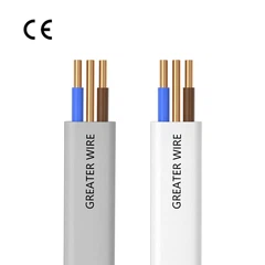
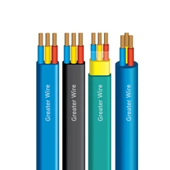
Cable Condition: Examine the entire length of the solar cable for any visible signs of damage, such as cuts, abrasions, or punctures in the insulation. Ensure that the insulation is intact and has not been compromised during installation.
Cable Routing: Check that the cables are routed in a manner that avoids sharp bends, kinks, or tight spaces. Ensure that the cables are not stretched or under tension, as this can damage the insulation and cause heat build-up.
Clearance and Support: Ensure that the cables are adequately supported along their route, whether they are placed in conduit, on cable trays, or secured with cable ties. Cables should be fastened at regular intervals to prevent sagging, rubbing against surfaces, or exposure to physical damage. Also, verify that cables have the appropriate clearance from heat sources, such as HVAC ducts or electrical panels, to avoid heat-related issues.
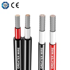
UV Protection: If the solar cables are routed in exposed areas, especially outdoors, confirm that they are UV-resistant. Cables should be rated for outdoor use, and the outer sheath should be intact and free from signs of UV degradation (e.g., cracking or brittleness).
2.2 Inspection of Cable Connections
Proper cable connections are vital for ensuring electrical safety and efficiency. Poor connections can lead to voltage drops, overheating, and increased risk of fire. The following aspects should be checked when inspecting the cable connections:
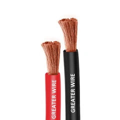
Connector Type: Ensure that the connectors used are designed for solar applications. They should be weather-resistant and rated for the voltage and current levels of the system. Solar cables typically use MC4 connectors, but other types such as Anderson or Amphenol connectors may also be used.
Tightness of Connections: Check that all cable connections are properly tightened. Loose connectors can cause arcing, which leads to heat buildup and eventual failure. Follow the manufacturer's recommended torque specifications to ensure connections are tight enough to prevent loosening over time but not so tight as to cause damage to the connectors.
Waterproofing and Sealing: Ensure that all connectors and junctions are waterproofed and sealed correctly. Water ingress into connections can lead to corrosion and failure of the cables. For outdoor systems, ensure that waterproof junction boxes and glands are used, and verify that they are sealed correctly to prevent moisture penetration.
Polarity and Correct Phases: In DC systems, ensure that the positive and negative cables are connected to the correct terminals. Incorrect polarity can lead to system malfunction and damage to the inverter or other components. Similarly, for AC systems, ensure that the phases are correctly identified and connected.
2.3 Voltage Drop Check
Voltage drop is an important factor that impacts the performance of a solar power system. If the cables are too long or too thin for the required current, there can be significant voltage drop, which reduces the efficiency of the system and increases energy losses.
Voltage Drop Calculation: Calculate the expected voltage drop based on the length of the cables and their cross-sectional area (gauge). Voltage drop can be estimated using the formula:
Voltage Drop=2×L×I×R/1000
Where:
LLL is the length of the cable (in meters),
III is the current (in amperes),
RRR is the resistance of the cable per meter (ohms).
Test Voltage: Perform a test of the system voltage at the solar panel end and the inverter end. The voltage difference should not exceed the maximum acceptable voltage drop (usually around 2-3%). If the voltage drop is too high, it may be necessary to upgrade the cables to a larger gauge or reduce the length of the cable run.
2.4 Insulation Resistance Testing
The insulation resistance of the cables should be tested to ensure that there is no leakage current that could lead to electrical hazards. A megohmmeter (insulation resistance tester) is typically used to perform this test.
Testing Procedure:
Disconnect the solar cables from the rest of the system to isolate them from any power source.
Use a megohmmeter to measure the insulation resistance between the conductor and the ground. The insulation resistance should typically be greater than 20 megaohms for low-voltage systems.
Result Interpretation: A low insulation resistance indicates that the insulation is damaged, which could lead to short circuits, leakage currents, or electric shocks. If the insulation resistance is low, inspect the cables for any physical damage, improper routing, or aging of the insulation, and replace any damaged cables immediately.
2.5 Thermal Imaging
Thermal imaging is a powerful tool for detecting potential issues with solar cables that might not be visible to the naked eye. It can identify areas where cables may be overheating, which is often a sign of poor connections or excessive current.
Procedure: Use a thermal camera to scan the solar cables and connectors while the system is operating. Pay special attention to areas with high current flow, such as junction boxes, cable connectors, and cable terminations.
Signs of Trouble: Hot spots on the cables indicate possible issues, such as loose connections, undersized cables, or faulty components. If hotspots are detected, perform a more thorough inspection of the affected area and rectify any issues, such as tightening connectors or replacing cables.
2.6 Earth Grounding Check
Grounding is essential for ensuring the safety of the solar power system and protecting it from electrical faults. Ensure that the solar cables are properly grounded according to local electrical codes.
Grounding Wire Inspection: Check the grounding wire for continuity and proper connection to the earth ground. Ensure that all metal parts of the solar panels, inverter, and other system components are securely connected to the grounding system.
Earth Resistance Test: Perform an earth resistance test using an earth ground resistance tester. The resistance should generally be less than 5 ohms for proper grounding.
2.7 Periodic Maintenance and Inspections
Once the solar cables have been installed and inspected, regular maintenance and inspections are necessary to ensure the system continues to perform optimally.
Routine Inspections: Conduct annual or semi-annual inspections of the solar cables to check for any signs of wear and tear, corrosion, or damage to connectors. Pay special attention to areas where cables are exposed to the elements, such as junction boxes, roof penetrations, and cable trays.
Cleaning: Ensure that the cables and connectors are free from dirt, debris, or corrosion that could affect their performance. Use a soft cloth or brush to clean any exposed cables, and avoid using harsh chemicals or abrasive materials that could damage the insulation.