


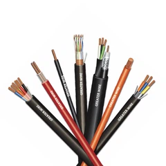


Orange circular cables are commonly used in various electrical and industrial applications, especially for power transmission, control systems, and signal transmission. These cables are recognized for their distinctive orange color, which helps ensure visibility and safety in environments such as construction sites, factories, and industrial plants. Like all cables, orange circular cables are susceptible to faults and damage due to physical stresses, environmental factors, or wear and tear over time. Detecting faults in these cables early is crucial for ensuring the continued safety and reliability of the electrical system.
In this article, we will discuss the common types of faults that can occur in orange circular cables, the techniques used to detect these faults, and best practices for maintaining the integrity of these cables.


What is an Orange Circular Cable?
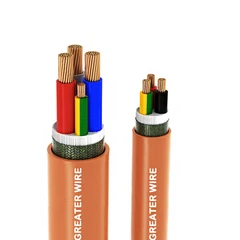
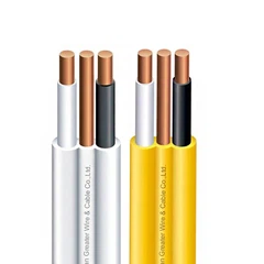
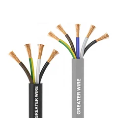
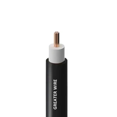
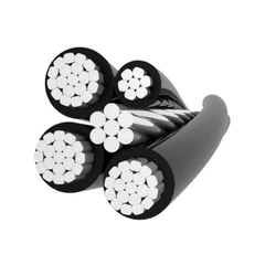
Before diving into fault detection, it's important to understand the basic structure of an orange circular cable. Typically, these cables consist of:
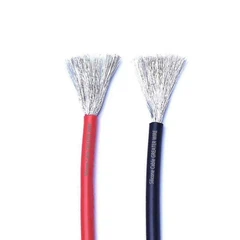
Conductors: These are the internal copper or aluminum wires that carry electrical current or signals. They are the core components of the cable and provide the path for power or communication.
Insulation: The insulation surrounds each conductor to prevent short circuits and leakage currents, providing electrical isolation between the wires.
Outer Sheath: The outer sheath is a protective covering that shields the internal components of the cable from mechanical damage, moisture, chemicals, and extreme temperatures. The orange color is used for visibility, especially in hazardous or high-traffic environments.
Despite their robust construction, orange circular cables are vulnerable to mechanical damage, electrical faults, or environmental degradation. Regularly checking for potential faults and taking proactive measures to detect them can help prevent accidents, improve system reliability, and extend the cable's lifespan.

Common Faults in Orange Circular Cables
Several types of faults can occur in orange circular cables, depending on the environment and operational conditions. These faults can be broadly classified into two categories: electrical faults and mechanical faults.
Electrical Faults
Short Circuits: A short circuit occurs when there is unintended contact between two or more conductors, leading to a direct path for the electrical current to flow. This can be caused by damaged insulation, leading to the conductors touching each other or the ground. Short circuits are dangerous and can cause overheating, system shutdowns, and even fires.
Open Circuits: An open circuit occurs when there is a break or discontinuity in one of the conductors, which prevents the current from flowing properly. This can be due to physical damage, conductor fatigue, or poor connection points.
Ground Faults: Ground faults happen when a conductor comes into contact with the ground or a grounded surface. This can lead to electrical shock hazards and system malfunctions. Ground faults are often caused by the deterioration of the insulation material or external damage to the cable.
Insulation Breakdown: Over time, the insulation on the cable can degrade due to thermal stress, chemical exposure, or mechanical damage. A breakdown of insulation can lead to leakage currents, electrical shorts, or even sparks, which can pose significant safety risks.
Voltage Fluctuations: An increase or decrease in voltage beyond the cable's rated capacity can cause damage to the insulation and lead to electrical faults. Voltage fluctuations can result from issues such as faulty power supplies, electrical surges, or overloaded circuits.
Mechanical Faults
Cracking or Splitting of the Outer Sheath: The outer sheath of the cable protects the internal components from mechanical damage. However, excessive physical stress, such as crushing or bending the cable, can cause the outer sheath to crack or split. Once the outer sheath is damaged, the internal conductors are more vulnerable to exposure and wear.
Abrasion: Continuous rubbing against rough surfaces can wear away the outer sheath and the insulation, exposing the conductors to environmental elements or mechanical damage.
Overheating: Cables that are exposed to excessive currents or are poorly ventilated can experience overheating. Overheating can lead to the breakdown of the insulation and conductor failure. It may also cause melting or charring of the outer sheath.
Physical Damage: Cables in environments with high mechanical stress, such as construction sites or factories, are at risk of physical damage from being crushed, stepped on, or bent beyond their recommended bend radius. Physical damage to the cable can lead to short circuits, open circuits, or insulation damage.

Techniques for Detecting Faults in Orange Circular Cables
Detecting faults in orange circular cables requires a combination of visual inspection, testing, and monitoring techniques. The goal is to identify potential issues before they lead to system failures or safety hazards. The following are some of the most common methods used to detect faults in these cables.
Visual Inspection
Visual inspection is one of the most straightforward and effective ways to detect faults in cables. While it may not detect all types of faults, it can help identify visible signs of damage, wear, or environmental degradation. Key indicators to look for include:
Cracks, cuts, or abrasions on the outer sheath or insulation.
Signs of overheating, such as discoloration, melted insulation, or charred areas.
Physical damage caused by crushing, bending, or impact.
Exposed conductors or frayed wires due to insulation breakdown.
Regular visual inspections should be part of a preventive maintenance routine to catch visible faults early. These inspections should focus on areas of the cable that are more vulnerable to wear, such as connectors, bends, and points of contact with surfaces.
Continuity Testing
Continuity testing is a simple and effective method for detecting open circuits, short circuits, or ground faults in the cable. This test involves checking if there is a continuous electrical path from one end of the cable to the other. A multimeter or continuity tester is used for this process.
Open Circuit: If the cable has a break or discontinuity in one of the conductors, the continuity tester will show an open circuit (i.e., no current will flow).
Short Circuit: If the conductors are shorted together, the tester will indicate continuity between the affected conductors, helping identify the fault location.
Ground Fault: In the case of a ground fault, a continuity tester can be used to check for continuity between a conductor and a ground. If continuity is detected, the cable is experiencing a ground fault.
Continuity testing is a quick and easy method for detecting major electrical faults. However, it may not provide detailed information about the condition of the insulation or other subtle issues.
Insulation Resistance Testing
Insulation resistance testing is a more advanced method used to assess the condition of the cable's insulation. A megger or insulation resistance tester is used to measure the resistance between the conductors and the ground. High resistance indicates that the insulation is intact and functioning properly, while low resistance suggests that the insulation is deteriorating or damaged.
This test is especially useful for detecting insulation breakdown, which can lead to leakage currents, ground faults, or electrical shocks. Insulation resistance testing should be conducted periodically, particularly in cables that are exposed to harsh environmental conditions, such as moisture, chemicals, or extreme temperatures.
Time-Domain Reflectometry (TDR)
Time-Domain Reflectometry (TDR) is a more sophisticated technique used to detect faults in cables, including both electrical and mechanical issues. TDR works by sending a pulse of electrical energy into the cable and measuring the time it takes for the pulse to reflect back. The time delay can be used to pinpoint the location of faults, such as open circuits, short circuits, or damaged sections of the cable.
TDR is a powerful tool for detecting faults in long cable runs, where visual inspection may not be feasible. It can identify faults that are difficult to locate, such as breaks in the conductor or insulation.
Thermography (Infrared Inspection)
Thermography, or infrared inspection, involves using an infrared camera to detect temperature variations in the cable. Overheating is a common sign of electrical faults, such as short circuits or overloading. By identifying hot spots in the cable, thermography can help detect areas of the cable that are at risk of failure due to excessive current or poor insulation.
Thermography is a non-contact and non-invasive method for detecting overheating in cables. It is particularly useful for detecting hidden faults that may not be visible during routine inspections.
High-Voltage Testing
In some cases, high-voltage testing is used to detect faults in cables. This test involves applying a higher-than-normal voltage to the cable and monitoring its response. High-voltage testing can reveal weaknesses in the insulation or points of failure that may not be apparent under normal operating conditions. However, this test should be conducted with caution, as it can put additional stress on the cable.

Preventive Measures to Avoid Faults
In addition to detecting faults, preventive measures should be taken to minimize the risk of damage to orange circular cables. These include:
Proper Installation: Ensure that cables are installed according to manufacturer specifications, with attention to bend radius, securing methods, and physical protection.
Protection from Environmental Elements: Use protective coatings or conduit to shield cables from moisture, chemicals, and UV radiation.
Avoid Overloading: Ensure that cables are not subjected to electrical loads beyond their rated capacity, as this can lead to overheating and insulation breakdown.
Regular Maintenance: Conduct regular inspections, testing, and maintenance to detect faults early and prevent serious issues.